Teledyne 9110TH - Nitrogen Oxides Analyzer User Manual
Page 37
Getting Started
Model 9110TH NOx Analyzer
Teledyne Analytical Instruments
17
E
M
IT
T
E
R BUS
F
O
R
PIN
S
1-8
STATUS
1 2 3 4 5 6 7 8 D
+
SY
STE
M
O
K
HI
G
H
RA
NG
E
C
O
NC
V
A
LID
ZE
RO CA
L
S
P
AN CA
L
D
IAGNOS
T
IC
MO
DE
LO
W
S
P
AN
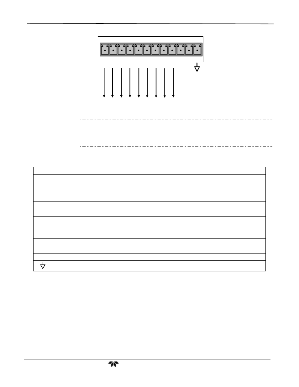
Figure 3-8:
Status Output Connector
Note
Most PLCs have internal provisions for limiting the amount of current the
input will draw. When connecting to a unit that does not have this feature,
external resistors must be used to limit the current through the individual
transistor outputs to ≤50mA (120 Ω for 5V supply).
Table 3-5: Status Output Signals
PIN #
STATUS
CONDITION (ON = CONDUCTING)
1
SYSTEM OK
ON if no faults are present.
2
CONC VALID
ON if concentration measurement (NO, NO
2
or NOx) is valid.
OFF any time the hold-off feature is active.
3
HIGH RANGE
ON if unit is in high range of the Auto Range Mode.
4
ZERO CAL
ON whenever the instrument is in ZERO point calibration mode.
5
SPAN CAL
ON whenever the instrument is in SPAN point calibration mode.
6
DIAG MODE
ON whenever the instrument is in diagnostic mode.
7
LOW SPAN CAL
ON when in low span calibration (optional equipment necessary)
8
Not Used
D
EMITTER BUS
The emitters of the transistors on pins 1-8 are tied together.
Not Used
+
DC POWER
+ 5 VDC, 300 mA (combined rating with Control Output, if used).
Digital Ground
The ground level from the analyzer’s internal DC power supplies