Connecting the control inputs – Teledyne 9110TH - Nitrogen Oxides Analyzer User Manual
Page 40
Model 9110TH NOx Analyzer
Getting Started
Teledyne Analytical Instruments
20
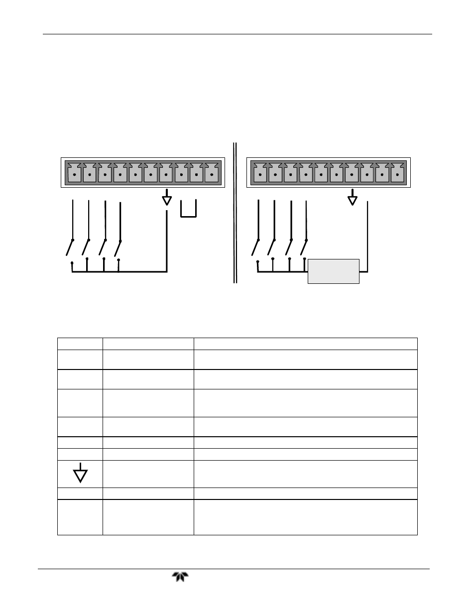
3.4.6. CONNECTING THE CONTROL INPUTS
Control Inputs are used to remotely activate the zero and span calibration modes. Locate
the 10-pin connector labeled CONTROL IN on the analyzer’s rear panel.
There are two methods for energizing the control inputs. The internal +5V available
from the pin labeled “+” is the most convenient method. However, if full isolation is
required, an external 5 VDC power supply should be used.
SPA
N
C
A
L
Z
E
RO
CAL
L
O
W
SPA
N
CONTROL IN
Local Power Connections
External Power Connections
S
P
AN CAL
Z
E
RO
CA
L
L
O
W
S
P
AN
CONTROL IN
-
+
5 VDC Power
Supply
A B C D E F U
+
A B C D E F U
+
R
ANG
E
HI
RAN
G
E
HI
Figure 3-10:
Control Input Connector
Table 3-6: Control Input Signals
INPUT #
STATUS DEFINITION
ON CONDITION
A
REMOTE ZERO CAL
The analyzer is placed in Zero Calibration mode. The mode field of
the display will read ZERO CAL R.
B
REMOTE SPAN CAL
The analyzer is placed in Span Calibration mode. The mode field of
the display will read SPAN CAL R.
C
REMOTE LO SPAN CAL
The analyzer is placed in low span calibration mode as part of
performing a low span (midpoint) calibration. The mode field of the
display will read LO CAL R.
D
REMOTE RANGE HI
The analyzer is placed into high range when configured for dual
ranges..
E SPARE
F SPARE
Digital Ground
The ground level from the analyzer’s internal DC power supplies
(same as chassis ground).
U
External Power input
Input pin for +5 VDC required to activate pins A - F.
+
5 VDC output
Internally generated 5V DC power. To activate inputs A - F, place a
jumper between this pin and the “U” pin. The maximum amperage
through this port is 300 mA (combined with the analog output supply,
if used).