Gas flow problems – Teledyne 9110TH - Nitrogen Oxides Analyzer User Manual
Page 230
Model 9110TH NOx Analyzer
Troubleshooting & Repair
Teledyne Analytical Instruments
210
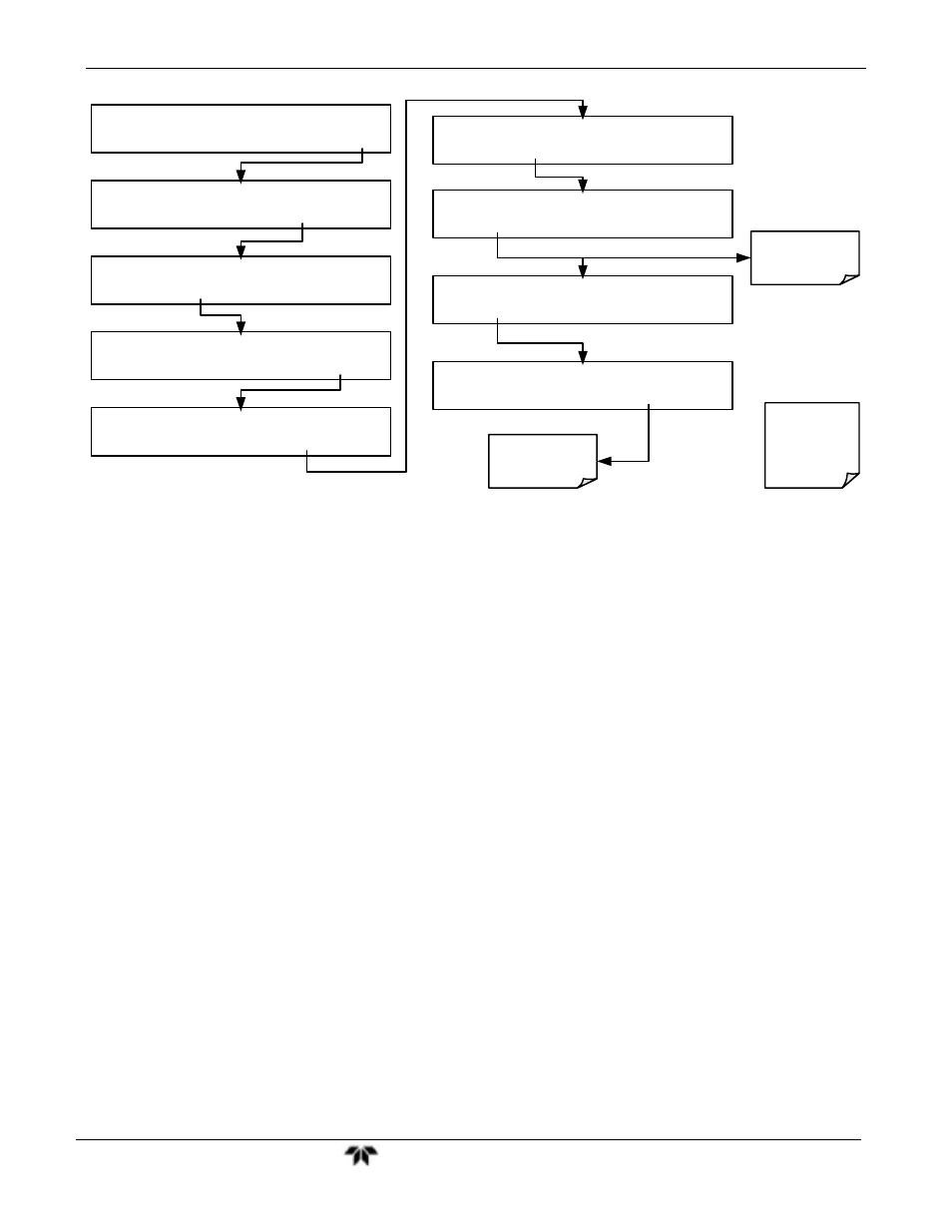
SAMPLE A1:NXCNC1=100PPM NOX=XXX.X
< TST TST > CAL
SETUP
SETUP X.X
PRIMARY SETUP MENU
CFG DAS RNGE PASS CLK
MORE
EXIT
SETUP X.X
SECONDARY SETUP MENU
COMM VARS
DIAG
ALRM
EXIT
SETUP X.X
ENTER PASSWORD:818
8
1
8
ENTR
EXIT
DIAG
SIGNAL I/O
NEXT
ENTR
EXIT
DIAG I/O
0) EXT_ZERO_CAL =OFF
NEXT
JUMP
ENTR EXIT
DIAG I/O JUMP TO:0
0
0
ENTR EXIT
DIAG I/O JUMP TO:25
0
7
ENTR EXIT
DIAG AIO 07) CAL_LED=ON
PREV NEXT JUMP
ON
PRNT
EXIT
Enter 07 to Jump
to Signal 7:
(CAL_LED)
Toggle to turn the
CAL LED ON/OFF
See Menu Tree
A-6 in Appendix
A.1 for a list of
I/O Signals
7.2. GAS FLOW PROBLEMS
The 9110TH/M has two main flow paths, the sample flow and the flow of the ozone
supply air. With zero/span valve option installed, there is a third (zero air) and a fourth
(span gas) flow path, but either one of those is only controlled by critical flow orifices
and not displayed on the front panel or stored to the DAS. The full flow diagrams of the
standard configuration and with options installed (Appendix D, document 04574) help in
trouble-shooting flow problems. In general, flow problems can be divided into three
categories:
Flow is too high
Flow is greater than zero, but is too low, and/or unstable
Flow is zero (no flow)
When troubleshooting flow problems, it is essential to confirm the actual flow rate
without relying on the analyzer’s flow display. The use of an independent, external flow
meter to perform a flow check as described in Section 4.13.7.5 is essential.
The flow diagrams found in a variety locations within this manual depicting the 9110TH
and 9110TM in their standard configuration and with options installed can help in
trouble-shooting flow problems. For your convenience they are collected here in
Sections 11.2.1 (9110TH) and 11.2.2 (9110TM)