Teledyne 9110TH - Nitrogen Oxides Analyzer User Manual
Page 229
Troubleshooting & Repair
Model 9110TH NOx Analyzer
Teledyne Analytical Instruments
209
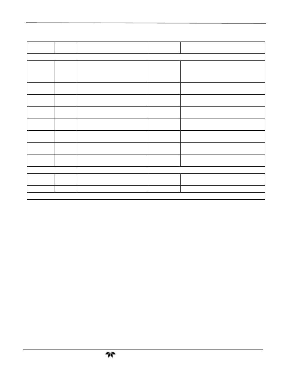
Table 7-2:
Relay Board Status LEDs
LED COLOR
FUNCTION
FAULT
STATUS
INDICATED FAILURE(S)
LED ROW 1
D1 Red
Watchdog Circuit; I
2
C bus
operation.
Continuously
ON or OFF
Failed or halted CPU; faulty motherboard,
keyboard, relay board; wiring between
motherboard, keyboard or relay board; +5
V power supply
D2
Yellow
Relay 0 - reaction cell heater
Continuously
ON or OFF
Heater broken, thermistor broken
D3
Yellow
Relay 1 - NO
2
converter heater
Continuously
ON or OFF
Heater broken, thermocouple broken
D4
Yellow
Relay 2 - manifold heater
Continuously
ON or OFF
Heater broken, thermistor broken
D7
1
Green
Valve 0 - zero/span valve status
Continuously
ON or OFF
Valve broken or stuck, valve driver chip
broken
D8
1
Green
Valve 1 - sample/cal valve status
Continuously
ON or OFF
Valve broken or stuck, valve driver chip
broken
D9
Green
Valve 2 - auto-zero valve status
Continuously
ON or OFF
Valve broken or stuck, valve driver chip
broken
D10
Green
Valve 3 - NO/NO
x
valve status
Continuously
ON or OFF
Valve broken or stuck, valve driver chip
broken
LED ROW 2
D6 Yellow
Relay 4 – (O
2
sensor heater
9110TH/M)
N/A N/A
D11- 16
Green
Spare
N/A
N/A
1
Only active for instruments with Z/S valve options installed
To enter the signal I/O test mode to manually control I/O functions such as valves and
heaters, press the following touch screen button sequence while observing the relay
board LEDs: