Sample gas flow – Teledyne 9110TH - Nitrogen Oxides Analyzer User Manual
Page 284
Model 9110TH NOx Analyzer
Principles
of
Operation
Teledyne Analytical Instruments
264
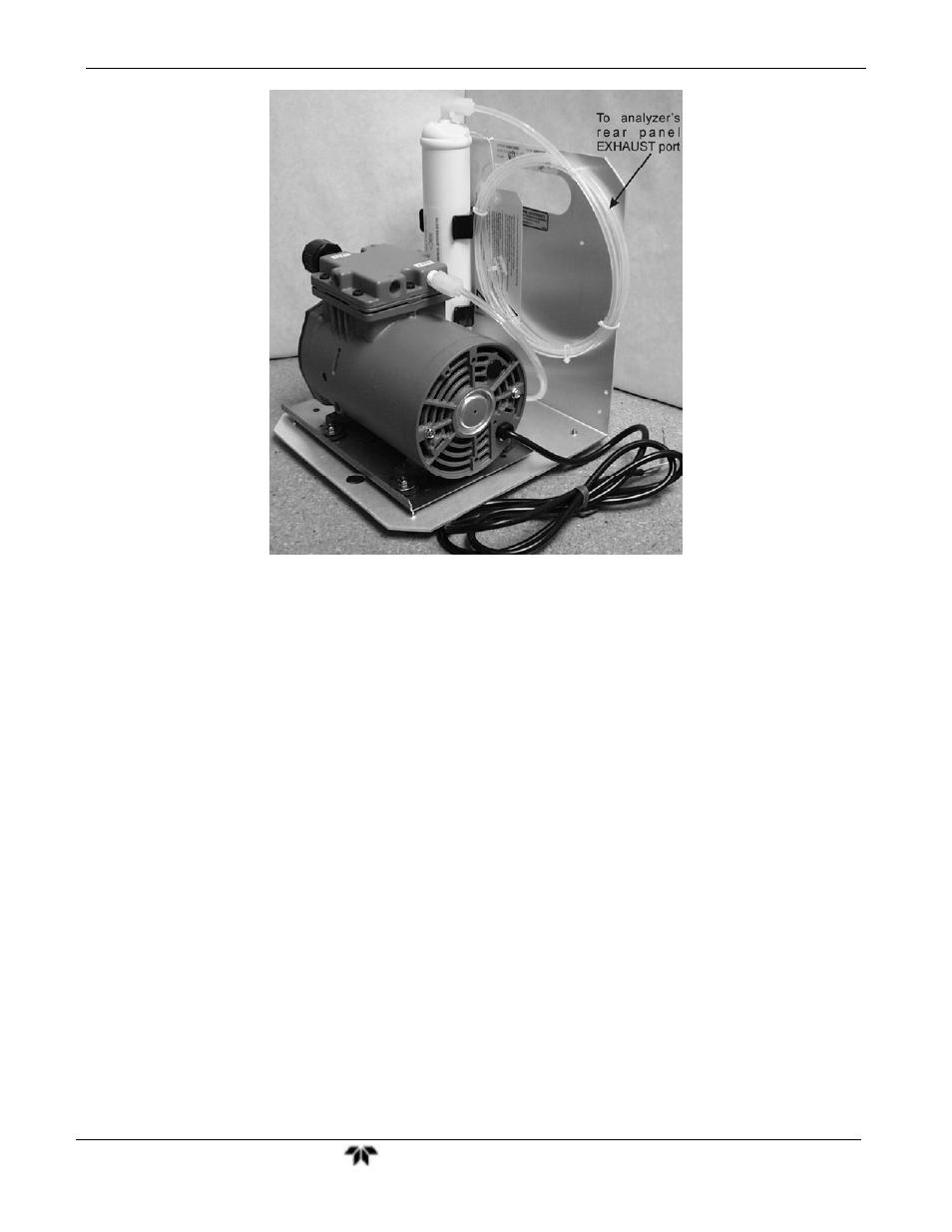
Figure 8-5:
External Pump Pack
Finally, the 9110TH/M requires a steady, high under-pressure, which cannot be achieved
reliably over extended periods of time with small vacuum pumps. The external pump
used for the 9110TH/M has a very long lifetime and duty cycle and provides a very good
vacuum for its entire lifetime. However, the pump is too large to fit into the chassis of
the analyzer.
8.3.2. SAMPLE GAS FLOW
The sample gas is the most critical flow path in the analyzer, as the medium has to be
routed through a variety of valves and tubes for the measurement of zero offset and
concentrations of both NO and NO
X
(and possibly the drying of the gas if the optional
sample dryer is installed). At any point before and in the reaction cell, the integrity of
the sample gas cannot be compromised.
Sample gas flow in the 9110TH/M analyzer is not a directly measured value, but is
rather calculated from the sample pressure using the flow principle across a critical
orifice. In general, the differential pressure ratio between sample pressure and reaction
cell pressure needs to exceed 2:1 to allow critical flow. The actual flow rate is then only
dependent on the size of the orifice and the upstream pressure. Refer to Section 8.3.3
for a detailed description of the instrument’s method of gas flow rate control.