Electronic operation, Pmt preamp pca, Pc 104 cpu card – Teledyne 9110TH - Nitrogen Oxides Analyzer User Manual
Page 299: Mother board
Troubleshooting & Repair
Model 9110TH NOx Analyzer
Teledyne Analytical Instruments
279
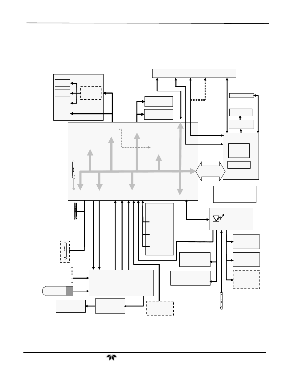
8.5. ELECTRONIC OPERATION
Figure 8-15 shows a block diagram of the major electronic components of the
9110TH/M.
Pneumatic
Sensor
Board
Sample
Pressure
Sensor
Vacuum
Pressure
Sensor
O
3
Flow Sensor
Analog Outputs
Status Outputs:
1 – 8
Control Inputs:
1 – 6
PC 104
CPU Card
Disk On
Module
Flash Chip
C OM1 (RS–232 ONLY)
COM2 (RS–232 or RS–485)
Power-Up
Circuit
I
2
C Bus
Analog
Sensor Inputs
Box
Temp
Thermistor
Interface
REACTION CELL
TEMPERATURE
MOLYBDENUM CONVERTER
TEMPERATURE
PMT
Temperature
Sensor
A1
A2
A3
Optional
4-20 mA
MOTHER
BOARD
A/D
Converter(
V/F)
PC 104
Bus
External
Digital I/O)
Analog
Outputs
(D/A)
RELAY
BOARD
I
2
C Status
LED
PUMP
(Externally Powered)
A4
CPU Status
LED
NO/NO
x
Valve
Autozero
Valve
Sample Cal
Valve Option
Option
Reaction Cell
Heater
Molybdenum
Converter Heater
PMT TEC
PMT
MOLYBDENUM CONVERT ER
TEMPERATUR E SIGNAL
TEC Drive
PCA
Internal
Digital I/O
EL
EC
T
R
IC
T
E
ST
C
O
N
T
R
O
L
O
P
TI
C
TE
S
T
CO
N
T
R
O
L
P
M
T O
U
TP
U
T
(
PM
T
D
E
T
)
O
2
Sensor
Option
H
IG
H
V
O
LT
AG
E
PO
W
E
R
S
U
PP
L
Y
LE
V
E
L
PM
T
T
E
M
PER
A
T
U
R
E
PMT
PREAMP PCA
O
2
OPTION
TEMPERATURE
Display
Touchscreen
LVDS
transmitter board
Analog RS232 COM2 USB Ethernet
IN
Male
Female COM port
USB
or USB
(I
2
C Bu s)
Figure 8-15:
9110TH/M Electronic Block Diagram
The core of the analyzer is a microcomputer (CPU) that controls various internal
processes, interprets data, calculates data, and reports results using specialized firmware
developed by Teledyne. It communicates with the user, receives data from and issues