Teledyne 9110TH - Nitrogen Oxides Analyzer User Manual
Page 155
Operating Instructions
Model 9110TH NOx Analyzer
Teledyne Analytical Instruments
135
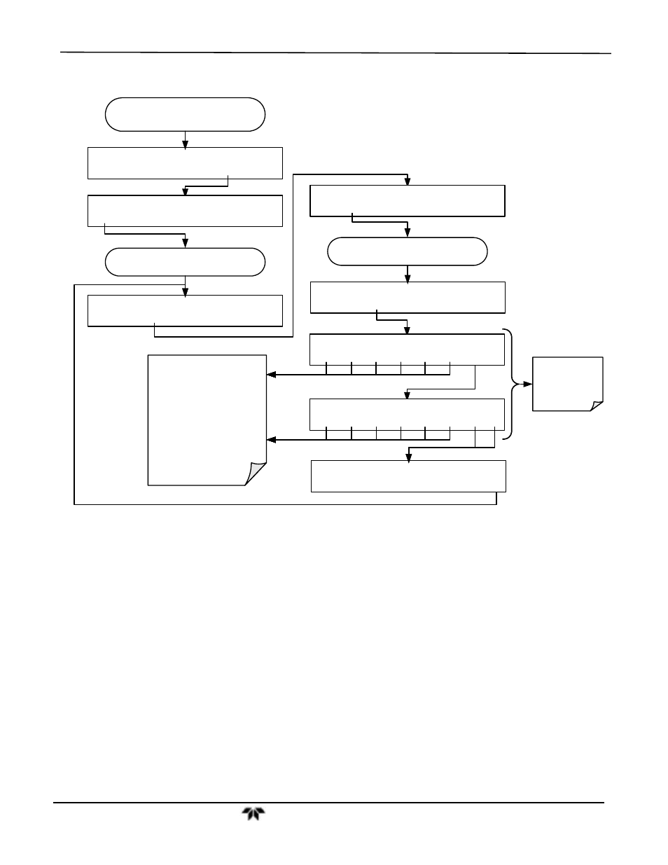
To manually adjust the signal levels of an analog output channel, press:
From the
AIO CONFIGURATION SUBMENU
(See Section 6.13.4.1)
DIAG
ANALOG I/O CONFIGURATION
PREV NEXT
ENTR
EXIT
Continue pressing SET> until you reach the
output to be configured
DIAG AIO DATA_OUT_2 5V, NXCNC1, NOCAL
EDIT
EXIT
Continue pressing SET> until ...
DIAG AIO DATA_OUT_2 CALIBRATED:NO
CAL
EXIT
DIAG AIO DATA_OUT_2 RANGE: 5V
SET>
EDIT
EXIT
DIAG AIO DATA_OUT_2 VOLT-Z: 0 mV
U100 UP10 UP DOWN DN10 D100 ENTR
EXIT
DIAG AIO DATA_OUT_2 VOLT-S: 4500 mV
U100 UP10 UP DOWN DN10 D100 ENTR EXIT
DIAG AIO DATA_OUT_2 CALIBRATED: YES
EXIT
These menus
only appear if
AUTO-CAL is
turned OFF
These buttons increase /
decrease the analog output
signal level (not the value on the
display)
by 100, 10 or 1 counts.
Continue adjustments until the
voltage measured at the output
of the analyzer and/or the input
of the recording device matches
the value in the upper right hand
corner of the display (within the
tolerances
listed in Table 6-24).
DIAG AIO AOUTS CALIBRATED: NO
SET>
CAL
EXIT
4.13.6.3. Manual Calibration of Analog Outputs Configured for Current Loop Ranges
The current loop output option (see Section 5.4) uses a small converter assembly to
change the DC voltage output by the standard voltage output to a current signal ranging
between 0-20 mA. Since the exact current increment per voltage count varies from
converter to converter and from instrument to instrument, analog outputs with this
option installed cannot be calibrated automatically and must be adjusted manually.
Adjusting the signal zero and full scale values of the current loop output is done in a
similar manner as manually adjusting analog outputs configured for voltage output
except that:
In this case calibration is performed with a current meter connected in series
with the output circuitry (See Figure 4-12).
Adjustments to the output are made using the front panel touch screen, also
in 100, 10 or 1 count increments, but the change in the voltage driving the
converter assembly is displayed on the front panel.