GF Signet 4632 Chlorine Dioxide Analyzer System User Manual
Page 4
4
463X Chlorine System Manual
Follow the steps below to set up a new Chlorine Analyzer System. Refer to the individual component manuals for detailed information.
Step 1. Mount the panel on a vertical À at surface using appropriate hardware.
Step 2. Open the wiring enclosure and wire input power
(see page 8: Wiring Input, page 9: Wiring Output, and page 10: Electrcial Box Wiring Schematic).
Step 3. Wire any 4 to 20 mA and relay output.
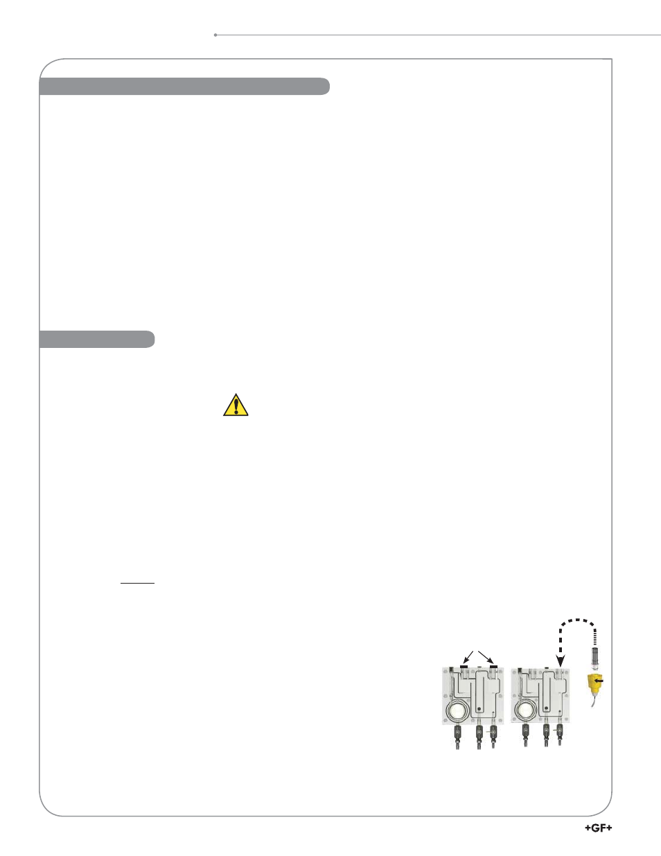
Step 4. Remove sensor access plugs from the À ow cell (Figure 1).
If the optional pH sensor is NOT used, do not remove the left-side plug from the À ow cell.
Step 5. Remove the protective cap from the chlorine electrode.
(Keep the electrode cap in a safe place for future use. It is recommended to use the cap to protect the sensor during
the removal of the electrode for cleaning or maintenance of the À ow cell).
Step 6. Complete Sensor Preparation (see page 11) and install the chlorine sensor into the electronics
(see page 12: Sensor Installation). Install the chlorine electrode into the À ow cell.
The chlorine sensor is installed in the right-side access port, optional pH sensor is installed in the left-side access port.
NOTE:
All new chlorine and pH sensors require calibration during the start up of a system and throughout the life of the sensor.
A new chlorine sensor requires a conditioning period of up to 4 hours with power on and chlorinated water À owing past
the sensor prior to calibration. See page 24: Chlorine Sensor Calibration, for chlorine calibration and set up procedure.
NOTE:
If a Chlorine Dioxide sensor or a Free Chlorine sensor without optional pH sensor is used, pH value must be
"hard-coded" into the system (See page 23: Manual pH compensation).
If optional pH sensor is installed, see page 22 to complete pH Sensor Calibration.
Step 7. Repeat step 5 and 6 if the optional pH sensor is being used.
Step 8. Install the inÀ uent water source to the "Inlet Port" nipple assembly of the À ow
cell. Install 3/8-inch tubing and secure with a hose clamp.
(Not included. See page 13: Tubing Connections)
Step 9. Install 3/8-inch tubing and secure with a hose clamp on the "Drain" port and
direct the tube to a proper drain. (Not included)
Step 10. Verify the inlet and drain ball valves are in the open position and
the sample port is in the off position (See page 13: Tubing Connections).
Step 11. Turn on the inÀ uent water source and check the system for leaks.
Step 12. Apply power to the system and allow system to initialize. Calibrate per instructions
(See page 24: Chlorine Sensor Calibration and page 22: pH Sensor Calibration).
NOTE:
As factory default, the 4630-X Chlorine Panel Assembly is set to measure Free Chlorine. If a 2632 Chlorine Dioxide
sensor is to be used to convert to a Chlorine Dioxide Panel Assembly, refer to the 8630-3 OPTIONS Menu on page 20.
Do not turn on power at this time.
1. Chlorine panel assembly
a. Built-in pressure regulator 15 to 120 psi.
b. 3/8 inch hose barb connectors.
2. 1 each 2630 series Free Chlorine sensor or 2632 Chlorine Dioxide sensor; each with protective cap
a. 1 spare membrane cap
b. 2 bottles of electrolyte solution
c.
1 syringe needle (taped to bottle)
d.
1
syringe
3. 1 each Flat pH sensor 3-2724-00 (159 001 545) (3-4630-11, -21, -31 and 3-4632-11 models only)
4. Manual
package
a. English panel assembly manual
b. CD with multi-language manuals
c.
Wall mounting hardware
d.
Drill
template
5. 1 each North American Type B power cord
6. Customer
supplied
a. 3/8" hose input and drain
b.
Hose
clamps
Sensor access plugs
Figure 1
System Inventory
Quick Start
4630 Chlorine Analyzer System Inventory