Transmitter terminals, Power supply 24 vdc terminal block, Electrical box wiring schematic – GF Signet 4632 Chlorine Dioxide Analyzer System User Manual
Page 10
10
463X Chlorine System Manual
Loop 2 -
Loop 2 +
System Power Loop 1 -
System Power Loop 1 +
AUX Power -
AUX Power +
Relay 2 (N.O.)
Relay 2 (COM)
Relay 2 (N.C.)
Relay 1 (N.O.)
Relay 1 (COM)
Relay 1 (N.C.)
Ground
Digital (S
3
L)
V+
Ground
Digital (S
3
L)
V+
Transmitter
Terminals
Signet Chlorine Sensor Electronics
3-2650-7 (159 001 670)
10
9
8
7
6
5
4
3
2
1
GND
10
9
8
7
6
5
4
3
2
1
GND
NO
COM RELAY 2
NC
NO
COM RELAY 1
NC
– LOOP 2
+ LOOP 2
– LOOP 1
+ LOOP 1
EARTH GROUND
Black
White
Yellow
Red
Signet pH Sensor Electronics
3-2750-7 (159 001 671)
Black
Black
Black
Black
Black
Black
Black
Black
Red
Black
White
Red
Black
White
GND
N
L
– V
+V
Power Supply
24 VDC
Terminal
Block
3-8630-3P (159 001 673)
Customer Wiring
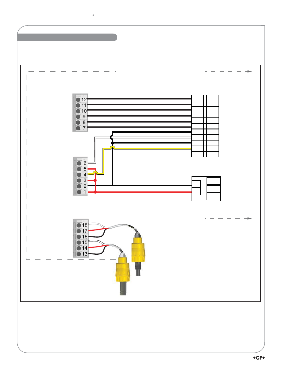
Electrical Box Wiring Schematic
Electrical Box Wiring Schematic
This manual is related to the following products: