GF Signet 4632 Chlorine Dioxide Analyzer System User Manual
Page 34
34
463X Chlorine System Manual
Appendix
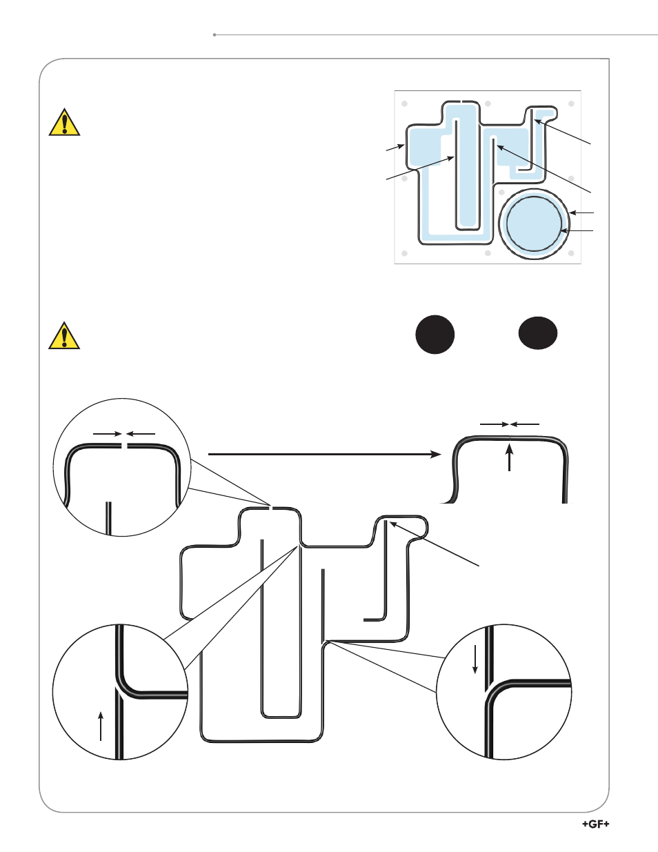
1
2
3
6
5
4
Individual O-rings shown.
Butt all segment joints together in ¿ nal assembly.
New O-ring
cross section
Old À attened O-ring
cross section
(Replace)
Fit À ush with no gap
Straight cut
Angle cut O-ring
Fit À ush with no gap
Angle cut O-ring
Fit À ush with no gap
Straight cut
Butt ends together
Fit all O-ring joints so there is no gap in ¿ nal assembly.
O-Ring Installation
• The sealing of the À ow cell is accomplished by four cut O-ring segments
and two round O-rings sealing the À ow regulator. Refer to the illustration
below for special O-ring ¿ tting instructions. Butt all O-ring joints together
so there is no gap.
• Remove the O-rings during À ow cell disassembly. Both the O-rings and all
sealing grooves should be examined for cleanliness.
• Wipe all surfaces carefully with a soft, lint-free cloth to ensure good sealing.
• The cross section of the O-rings should be round and smooth. If they are
À attened, their ability to seal is reduced.
• Do not use liquid or paste sealant.
Do not scratch the sealing surfaces of the À ow cell block.
Scratches to the sealing surfaces can cause irreparable leaks.
CAUTION!
The 3-4630.390 (159 001 688) O-ring kit
comes complete with two O-rings (5 and 6) and a
single cord of material that must be cut and ¿ tted
into the O-ring groove of the À ow cell (1 and 4).