GF Signet 4632 Chlorine Dioxide Analyzer System User Manual
Page 28
28
463X Chlorine System Manual
CAUTION!
• Remove power before wiring.
• Follow instructions carefully to avoid personal injury or
damage to the electronics.
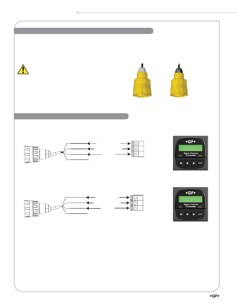
• Refer to the wiring diagram above to connect the 2650 cable to the terminals on the 8630 Chlorine Transmitter.
• For calibration and con¿ guration please refer to the 8630 Calibrate Menu discussions above.
The electronics are pre-wired from the factory to the transmitter. Refer to the following
schematics when replacing the electronics.
8630
Chlorine
Gnd
I/O
V
+
18
17
16
Signal Ground
Digital (S
3
L) data
+5 VDC
White
Red
Black
Shield
pH
Signet 3-2750-7
(159 001 671)
N/C
8630
Chlorine
Gnd
I/O
V
+
15
14
13
Signal Ground
Digital (S
3
L) data
+5 VDC
White
Red
Black
Shield
Chlorine
Signet 3-2650-7
(159 001 670)
N/C
• The Signet 2650-7 Amperometric Electronics provide the polarization voltage and signal conditioning required by the Signet
2630-X and 2632-X Sensors.
• The Signet 2750-7 pH Electronics conditions and ampli¿ es the output from the Signet 2724-00 pH Electrode.
• Both units output a Digital (S
3
L) signal to the Signet 8630 Chlorine Transmitter.
2650-7 and 2750-7 Electronics
2650-7 Amperometric and 2750-7 pH DryLoc
®
Electronics
Wiring to the Signet 8630 Chlorine Transmitter