Electrical connection to the position controller, Type 8791 or type 8792/8793 – Burkert Type 8798 User Manual
Page 33
33
Electrical Installation
10.2. electrical connection to the
position controller Type 8791 or
Type 8792/8793
procedure:
→
If necessary, shorten the cable of the Remote Sensor and connect
it to the M12 cable gland on the position controller Type 8791 or
Type 8792/8793.
→
Connect the 4 wires of the cable, as described in “Tab. 6” and in
the operating instructions of the position controller Type 8791 or
Type 8792/8793, to the appropriate terminals (Chapter "
Terminal
assignment for external position sensor" in the operating instruction
of Type 8791 or Type 8792/8793).
terminal
Wire color
configuration
external circuit
8791 or
8792/8793
for cable type
1
2
1
white black
Supply
sensor -
S –
2
brown
Supply
sensor +
S +
3
yellow orange Serial interface
B cable
B
4
green red
Serial interface A
cable
A
Tab. 6: Wire color - configuration with screw-type terminals
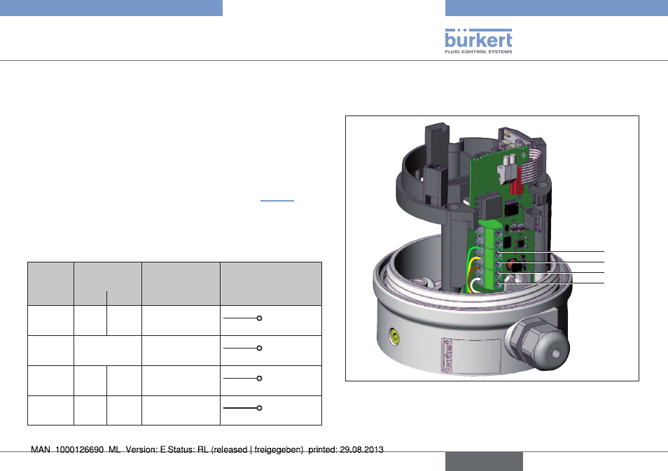
10.2.1. Terminal configuration linear remote
sensor
4
3
2
1
Fig. 33: Terminal Configuration linear Remote Sensor
English
Type 8798