Electrical data, Control and display elements, Display elements of the linear remote sensor – Burkert Type 8798 User Manual
Page 11
11
Control and display elements
6.7.
electrical data
Connections:
Linear Remote Sensor:
Round cable 10 m
Rotating Remote Sensor:
Round cable 2 m shielded (maximum
extension 10 m)
Power supply:
(via the position controller Type 8791 or
Type 8792/8793)
Linear Remote Sensor:
24 V DC ± 10 %
Rotating Remote Sensor:
10 ... 30 V DC
Power consumption:
Linear Remote Sensor:
< 0.3 W
Rotating Remote Sensor:
< 0.8 W
Protection class:
3 in accordance with VDE 0580
Communication:
via serial interface RS485 (included in the
supply cable)
7.
cOnTrOl and display
elemenTs
Special operation of this Remote Sensor is not necessary. The nec-
essary settings are made on the position controller Type 8791 or Type
8792/8793 (see relevant chapter of the position controller operating
instructions).
7.1.
display elements of the linear
remote sensor
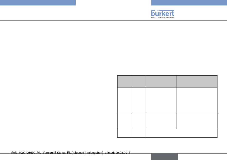
2 LEDs, which are also visible from outside through the transparent
hood, display the sensor mode.
status
led 1
yellow
status
led 2
red
display
remedial action
off
off
No operating
voltage
Check the power supply
of position controller
Type 8791,
Type 8792/8793.
Check the cable con-
nection configuration.
flashing on
Sensor is operated
outside the cov-
erage area.
Check adaption to drive;
the puck on the switch
spindle must not exceed
the sensor surface.
flashing off
Sensor is in operation and sending position
value
Tab. 1: LED display elements; linear Remote Sensor
English
Type 8798