Display elements of the rotating remote sensor – Burkert Type 8798 User Manual
Page 12
12
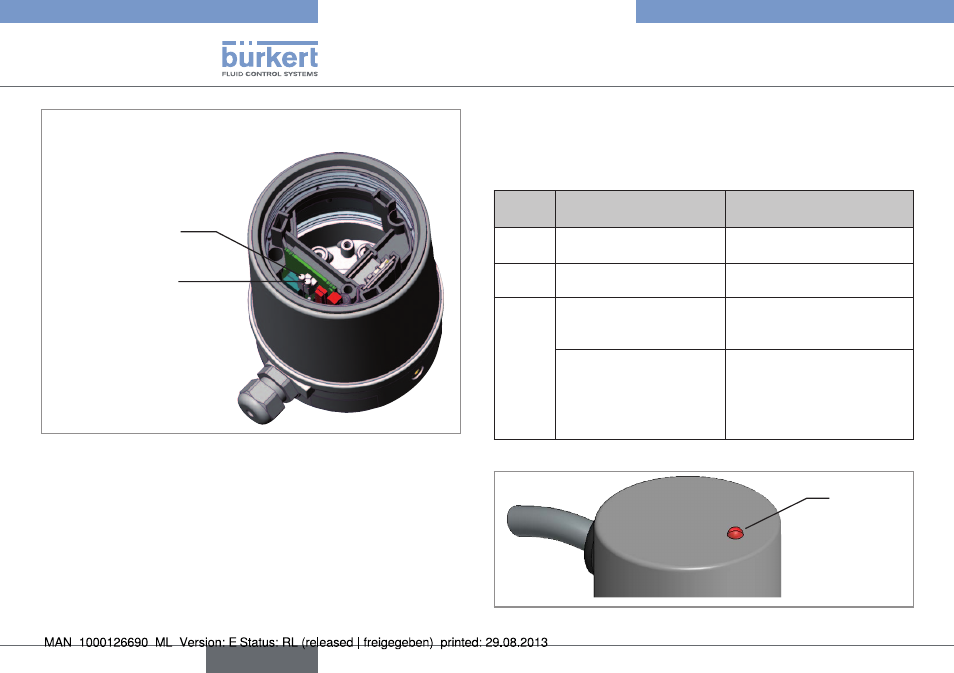
Control and display elements
Status LED red
Status LED yellow
View without transparent hood
Fig. 5:
LED display elements; linear Remote Sensor
7.2.
display elements of the rotating
remote sensor
An LED on the upper side of the sensor housing is used to indicate
the sensor mode.
status
led
display
remedial action
off
No operating voltage
Check power supply,
connection.
on
(yellow)
Ready for operation
-
on
(red)
Starting phase
(during the acceleration
phase – booting)
-
Sensor error
Switch off the operating vol-
tage and switch it on again.
The sensor is defective if the
display continues to show
“Sensor error”.
Tab. 2: LED display elements; rotating Remote Sensor
Status
LED
Fig. 6:
LED display elements; rotating Remote Sensor
English
Type 8798
See also other documents in the category Burkert Sensors:
- Type 1062 (112 pages)
- Type 1050 (4 pages)
- Type 8750 (64 pages)
- Type 8750 (82 pages)
- Type 8681 (90 pages)
- Type 8681 (40 pages)
- Type 8798 (2 pages)
- Type 8791 (4 pages)
- Type 8792 (118 pages)
- Type 8791 (15 pages)
- Type 8792 (136 pages)
- Type 8792 (252 pages)
- Type 8718 (34 pages)
- Type 8791 (154 pages)
- Type 8791 (106 pages)
- Type 8791 (184 pages)
- Type 8791 (28 pages)
- Type 8791 (21 pages)
- Type 0911 (46 pages)
- Type 0911 (64 pages)
- Type 0911 (84 pages)
- Type 0911 (76 pages)
- Type 1058 (31 pages)
- Type 1060 (4 pages)
- Type 1066 (112 pages)
- Type 1067 (158 pages)
- Type 1077-2 (33 pages)
- Type 1094 (41 pages)
- Type 1094 (82 pages)
- Type 1094 (126 pages)
- Type 1094 (12 pages)
- Type 1115 (25 pages)
- Type 1150 (99 pages)
- Type 1541 (2 pages)
- Type 5142 (6 pages)
- Type 8619 (40 pages)
- Type 8619 (134 pages)
- Type 8620 (177 pages)
- Type 8622 (4 pages)
- Type 8623 (130 pages)
- Type 8623 (90 pages)
- Type 8625 (118 pages)
- Type 8624 (124 pages)
- Type 8718 (1 page)