Burkert Type 8798 User Manual
Page 26
26
Installation
→
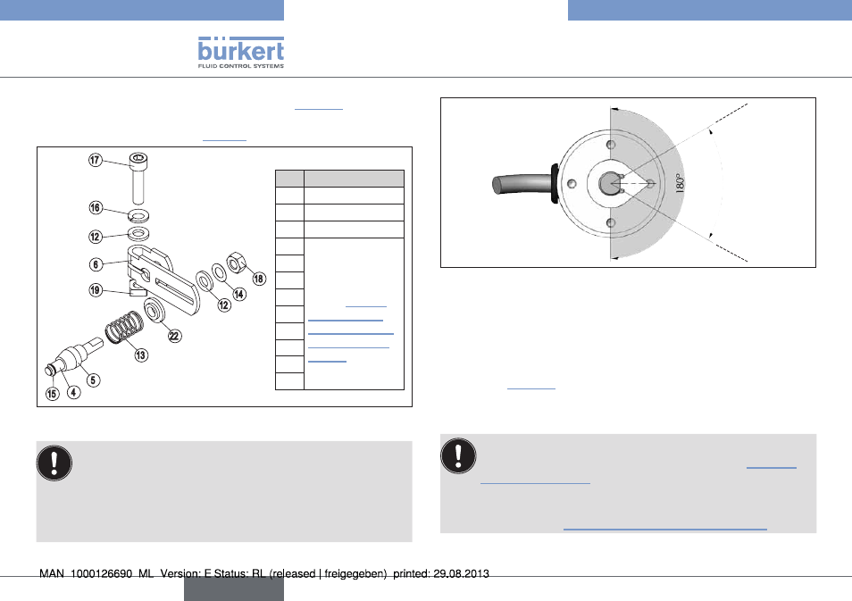
Assemble lever (if not pre-assembled) (see “Fig. 25”).
Depending on the stroke range, a short or long lever is required
for the installation (refer to “Tab. 4”)
Legend:
no. name
4
Driver pin
5
Conical roller
6
Lever
12
For a description
of the numbering,
refer to “Tab. 4:
Mounting kit to
push actuator for
rotating Remote
Sensor”
13
14
15
16
17
18
19
22
17
16
12
6
19
18
14
12
22
5
4
13
15
Fig. 25: Assembling the lever
The gap between the driver pin and the shaft should be
the same as the actuator stroke. As a result, the lever has a
swivel range of 60°.
swivel range of the lever:
To ensure that the position sensor operates at a good reso-
lution, the swivel range of the lever must be at least 60°.
60°
Swivel range of the
lever
Fig. 26: Swivel range of the lever
→
Attach lever to the shaft of the rotating Remote Sensor and
tighten.
→
Attach mounting bracket
①
with hexagon bolts
⑨
, circlips
⑩
and washers
⑪
to the support plate of the Remote Sensor
→
To determine the correct position, hold the rotating Remote
Sensor to the actuator.
The conical roller
⑤
on the lever
⑥
of the position sensor
At 50% stroke the lever position should be approximately
horizontal (see “Aligning lever mechanism:”, page 28).
English
Type 8798