Figure 2.4-5 ts-1001 / 2001, Lldi wiring diagram - 5, Tb1 tb2 – Franklin Fueling Systems TS-LLD Installation Manual User Manual
Page 53: Ts-lldi ( line leak detector interface )
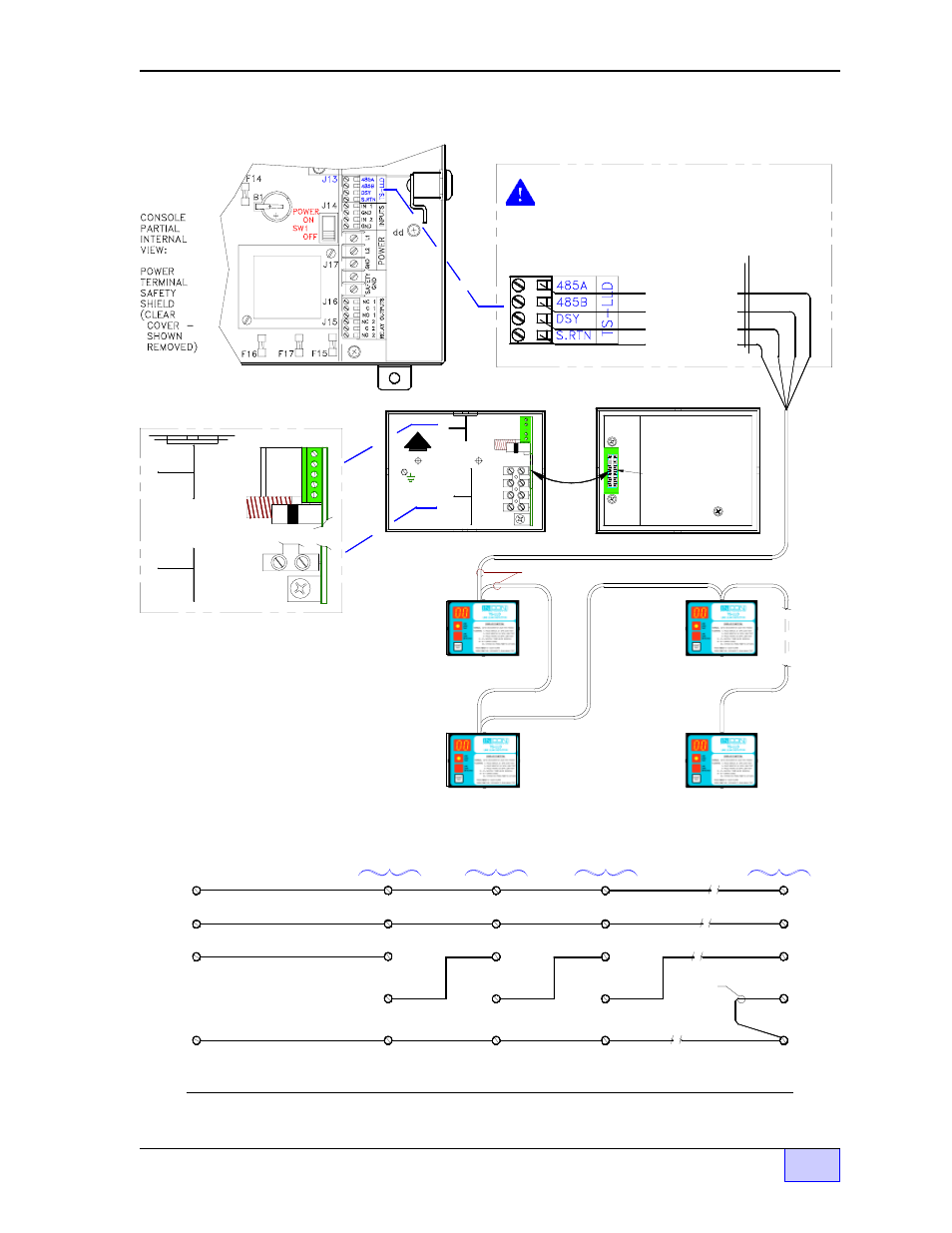
TS-LLD – Tank Sentinel ATG Console Interface
NOTE:
1) CAUTION
BEFORE attempting this
installation: Read and reference the TS-LLD Manual
about Safety, and CU Installation (and wiring steps).
2)
WARNING
Avoid electrical shock hazards —
Turn off and disconnect all power to the pumps and
dispensers before wiring at the TS-LLD Control Units.
3) Up to four TS-LLD Control Units ( CUs ) can be
interfaced to the TS-1001 console and up to eight CUs
can be interfaced to the TS-2001 console.
Figure 2.4-5 TS-1001 / TS-2001 LLDI Wiring Diagram
TANK / LINE #2
TS-LLD CU #2:
TB2-3 DSY1
TB1-SIG RTN
TB2-4 DSY2
TB2-2 485B
TB2-1 485A
CU #2
CU #1
1 485A
2 485B
3 DSY1
4 DSY2
5 ALARM
SIG RTN
4 P-IN
3 P-OUT
2 NEU
1 110V
TS-LLD Control Unit (CU) box
TS-1001 / 2001 CONSOLE
TS-LLD INTERFACE
TERMINALS AT J13:
DSY
CONTROL UNIT I.D. LINE
S. RTN
RS-485 COMMUNICATIONS
SIGNAL RETURN
485B
COMM LINE
485A
COMM LINE
TB2-3 DSY1
TB1-SIG RTN
TB2-4 DSY2
TANK / LINE #1
TS-LLD CU #1:
TB2-2 485B
TB2-1 485A
F1
1 485A
2 485B
3 DSY1
4 DSY2
5 ALARM
4 P-IN
SIG RTN
TB1
TB2
Enlarged View
TS-LLD Control Unit (CU)
Interface Terminals:
TB1
UP
GND
TB2
TB2-4 DSY2
TB2-3 DSY1
TB1-SIG RTN
TANK / LINE #3
TS-LLD CU #3:
TB2-2 485B
TB2-1 485A
TB2-3 DSY1
TB1-SIG RTN
TB2-4 DSY2
JUMPER
NEEDED
AT LAST
UNIT
ONLY
LAST TANK / LINE #N
TS-LLD CU #N:
TB2-2 485B
TB2-1 485A
...NOTE --- DO NOT RUN
COMMUNICATIONS
CABLE IN SAME CONDUIT
AS LINE VOLTAGE WIRES.
last CU #N
CU #3
THIS SHIELD MUST BE
IN PLACE BEFORE THE
COVER IS RE-INSTALLED.
GREEN CONNECTOR (J1)
TS-LLD CU cover (back view)
COMMUNICATIONS CABLE: 22 AWG, 4 CONDUCTOR...
F1
W A R N I N G: AVOID ELECTRICAL SHOCK HAZARDS.
EXTERNAL POWER SOUCES MAY BE PRESENT -
LOCATE AND DISCONNECT ALL EXTERNAL POWER
SOURCES BEFORE WIRING OR SERVICING
THESE CIRCUITS.
TS-LLDI ( Line Leak Detector Interface )
TB1-SIG RTN
TB2-1 (485A)
TB2-2 (485B)
TB2-3 (DSY 1)
Enlarged View of
Terminal Strip # J13