Note 2.3, Note - 4 – Franklin Fueling Systems TS-LLD Installation Manual User Manual
Page 38
Control Unit Installation Steps (continued...
)
5) Wiring at the Pump Control Relay Box:
a) Remove the wire from S2 to the relay coil
b) Remove the wire from M2 to the relay N.O. contact
c) Install the 1µ Farad “Line Filter” capacitor (INCON P/N 020-0028) between
terminals L1 and L2
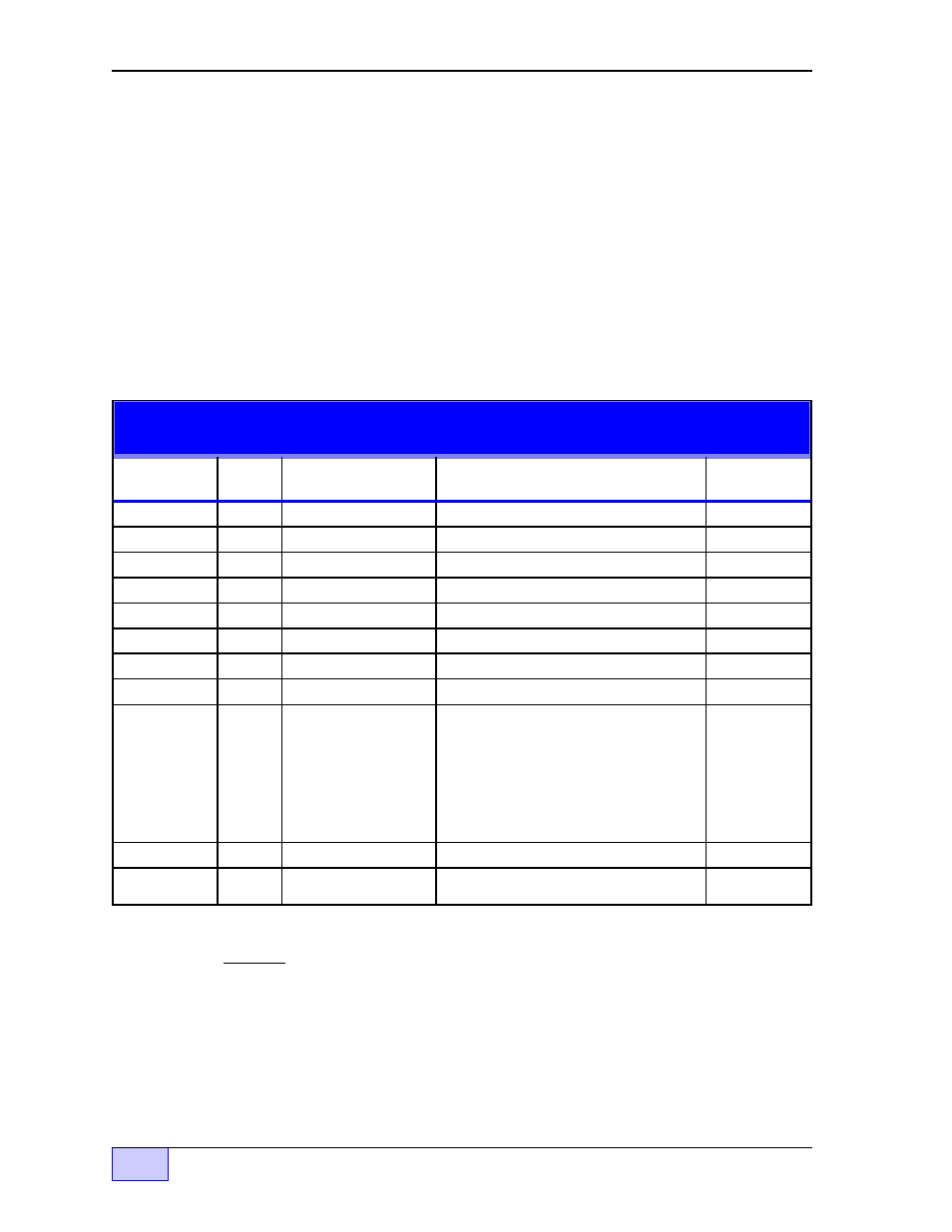
d) Wire the CU to the pump relay box as described below TABLE 2.3-1 and as
shown in
Figures 2.3-4 & 2.3-5. Strip 1/4 inch of insulation off each end (for
termination at the control unit and for the spade crimp connectors at the pump
relay box). Use connectors sized for 14 AWG wire.
Other pump relay boxes may have different terminations, and/or may
be wired differently than what is shown in this manual.
Typical Single Phase Wire Connection List TABLE 2.3 -1
PUMP RELAY BOX — to — TS-LLD CONTROL UNIT ( CU )
P-OUT (Pump On - output signal,
{ Pump Motor Power - the 14 gauge
orange wire is pre-routed through the
pick-up coil at the Control Unit.
relay box, wire one end to the M2
terminal, & wire the other end to the
pump relay N.O. contact (Figure 2.3-
4)... no wiring/connection at CU
Electricians:
All AC wiring at the control unit (TB1-1 110V and TB1-4 P-IN)
must be in-phase and read 0 VAC in respect to each other and must read
from 110 to 130 VAC in respect to ground. Reference Figures 2.3-4 thru
2.3-10. These are “typical” diagrams and may not represent the actual wiring.
A
0 VAC potential must exist from TB1-1 to the hot side of dispenser on switch S1
( or to
S2 ) with the dispense switch on. Take voltage readings at the pump relay
box. Use the leg that is in-phase with
S1 ( L1 or L2 that reads 0 VAC) and wire it
to
TB1-1 ( 110V ).
For 3 phase applications —
DO NOT use any leg that
reads more than 130 VAC to Ground !
NOTE
☞
NOTE
☞