Figure 2.2-15 incon ts-lld installation at bigflo, Diaphragm valve -14 & 2.2 - 15 – Franklin Fueling Systems TS-LLD Installation Manual User Manual
Page 32
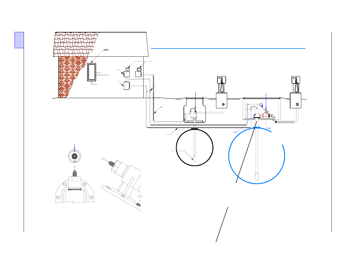
INCON TS-LLD Line Leak Detector
BigFlo & Diaphragm Valve Installation
Tank - Pump # 1
("Standard" Single Phase
Installation)
TS-LLD LSU (#1)
(Leak Sensing Unit)
at pump housing
Standard Single
Phase Installation
NOTE:
1)
2)
An additional Single Phase 230 VAC
Relay Control Box (panel), two additional
wires, and possibly an additional conduit run to
the LSU, are required for 3 Phase Applications.
The INCON TS-LLD LSU MUST be installed
so the fasteners are aligned in a 12 & 6 o'clock
(vertical) position as shown in Detail A - A.
Tighten the LSU to meet this requirement.
Detail A - A
Overhead Top View
(correct alignment)
Partial
Enlarged
Side View
Submerged
Turbine
Pump (STP)
Existing
Conduit
(Pump 2)
Electrical
Power Panel
Pump
Relay
Boxes
3 Phase
Pump
Motor
Starter
TS-LLD CUs
(Control Units):
# 2 and # 1
2
1
2
Epoxy
Filled
EYS
Seal
Fittings
Existing
Conduit
(Pump 1)
Tank - Pump # 2
(BigFlo Three Phase Pump and
Diaphragm Valve Installation)
BigFlo Pump
Note:
Use two
conduits
when
conduit
fill exceeds
40% full as
specified
by your
National
Electric
Code.
Explosion-
proof
Junction
Box . . . . .
TS-LLD LSU (#2)
(Leak Sensing Unit)
at Diaphragm Valve
see Detail A - A
Dispenser
# A
BigFlo
STP
Pump
Dispensers
# B thru # X