Interface schematic - 9, Reference schematic, Figure 2.3 - 8 – Franklin Fueling Systems TS-LLD Installation Manual User Manual
Page 43: Control unit installation page 2.3 - 9
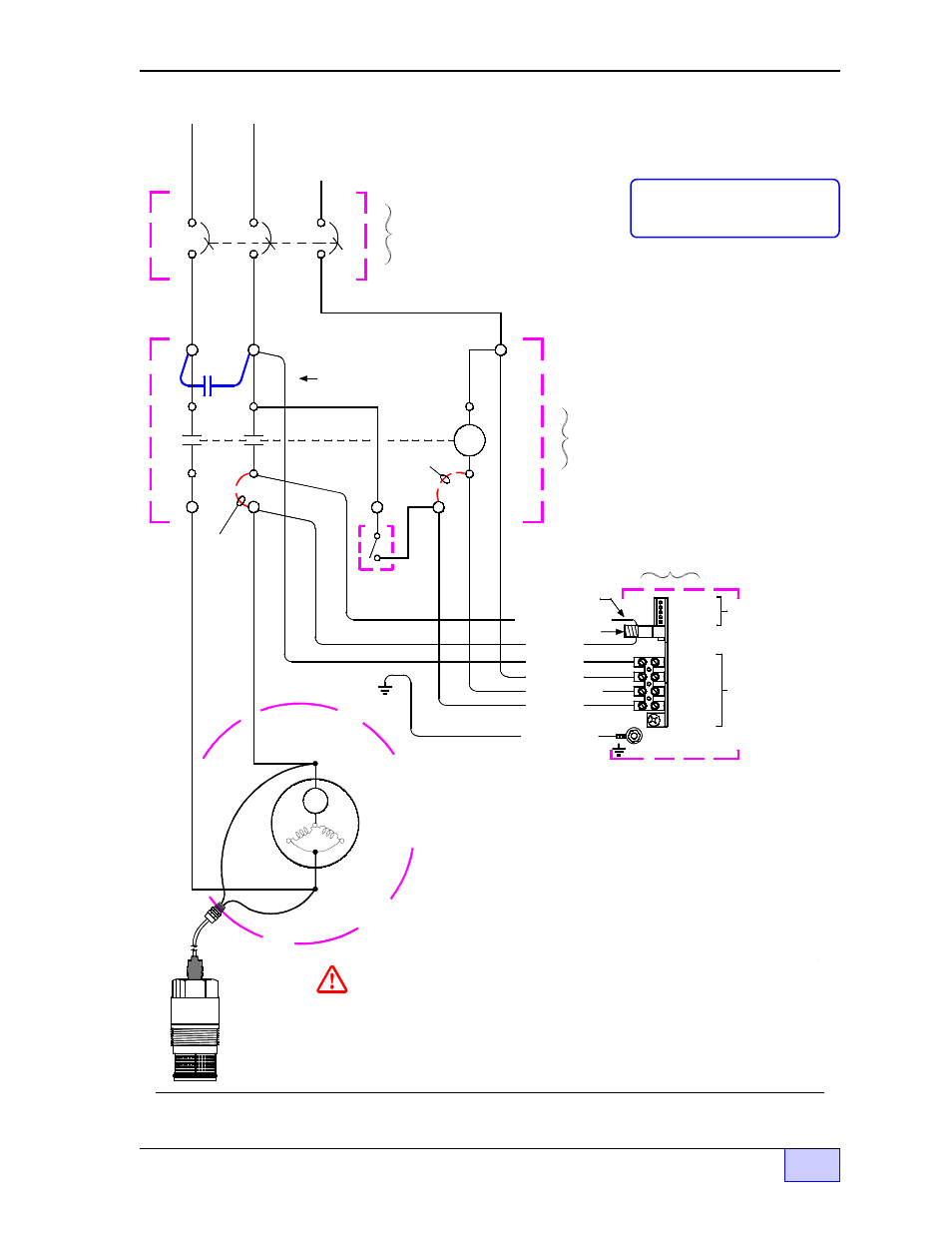
Figure 2.3-8 Three Phase 240 VAC Supply – Single Phase 240 VAC Pump & Control Unit
N
Pickup Coil
Remove
Original
Wiring
COIL
115 V.
Dispenser
Switch
(or switches)
S2
S1
Remove
Original
Wiring
RLY N.O. Contact
L2 (BLK)
N (WHT)
TB1
TB2
1 485A
2 485B
3 DSY1
4 DSY2
1 110V
2 NEU
5 ALARM
3 P-OUT
SIG RTN
4 P-IN
F1
MI Cable
Adapter
(cover) for
Explosion
Proof
junction box
Single Phase
Submersible
Pump Motor
with
Thermal
Overload
BLK
BLK
TS-LLD Leak
Sensing Unit
(Installed at
the pump
housing.)
OL
DANGER ELECTRICAL SHOCK HAZARDS. TURN OFF AND LOCK-OUT THE
SUBMERSIBLE PUMP POWER SOURCE, AND THE PUMP RELAY POWER SOURCE
AT THE CIRCUIT BREAKER - BEFORE - WORKING ON THIS EQUIPMENT. FAILURE
TO TURN OFF THESE POWER SOURCES WILL RESULT IN SEVERE INJURY OR DEATH.
Line Filter Cap
(See Note 2)
ON
OFF
LINE
LOAD
L2
208/230 Volt, Single Phase,
Electrical Power Panel
3 Pole Switched-Neutral
Circuit Breaker
See
Note
1
L2
L1 ( or L3)
Neutral Bus
See
Note
1
L1
(or L3)
208/230 Volt, Single Phase -
Submersible Pump Motor
Relay Box
TS-LLD Control Unit
(use bottom, 1/2 inch
conduit knockout)
From: 208/230 Volt, Three Phase, Electrical Power Source,
utilizing two lines to power a Single Phase load.
(See Note 1)
NOTES:
1) Only use phases L1 & L2, or L3 & L2. DO NOT use
phase L1 & L3.
2) Install the 1uF Line Filter Capacitor (INCON PN 020-0028)
between AC input line terminals at the Relay Box.
3) The TS-LLD is installed at the submersible pump housing
(see Chapter 2.2 for details).
4) Follow your local and National Electrical Codes for
electrical grounding requirements.
5) 230 VAC must not enter the Control Unit! All Control Unit
AC wiring must be 110 volts (110V power = TB 1-1, dispenser
switch [ S2 ] on signal = TB 1-4, and pickup coil [ M2 ] sense
lead all must be derived from the same phase [ L2 ] ).
M2 (ORG)
No connection
at CU -- wire is
run through the
donut-shaped
Pickup Coil
GROUND (GRN)
#8-32 Ground Stud
GROUND
M2
M1
COM
N.O.
COM
N.O.
S2 (BRN)
RLY COIL (RED)