Figure 2.3-7 mechanical blender dispensers to, Ts-lld control unit interface schematic - 8, Ts-lld line leak detector – Franklin Fueling Systems TS-LLD Installation Manual User Manual
Page 42: Mechanical blender interface, Dispense on
TS-LLD Line Leak Detector
—
Mechanical Blender Interface
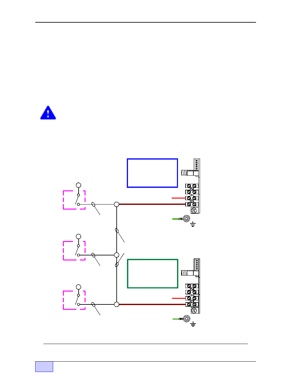
When connecting a TS-LLD line leak detector to systems with mechanical
blenders, tie the: premium, all mid-grades, and regular dispenser switch signals
together (electric blenders can be wired normally). Wire both premium and
regular TS-LLD Control Units at TB1-4 (P-IN). See the typical (partial) wiring
diagram below. Because the mid-grades are blended mixtures of the premium
and regular octanes, any product dispense will abort leak tests at the premium
and regular Control Units.
CAUTION The
dispense on
signals must be
in phase
to avoid electrical shorts
and damage. Verify that all dispenser switch signals are in phase before you tie
them together (in phase = 0 Volts AC in respect to each other and 120 Volts AC in
respect to Neutral or ground). Note that both pumps will be active on any
dispense.
PREMIUM
TS-LLD
Control Unit
REGULAR
TS-LLD
Control Unit
TO: REGULAR MOTOR
START RELAY COIL
TO: PREMIUM MOTOR
START RELAY COIL
REGULAR
Dispense
Switch (es)
MID-GRADE
Dispense
Switch (es)
S1
N.O.
C
N.O.
C
Dispense
(on) signal
Dispense
(on) signal
Tie
together
PREMIUM
Dispense
Switch (es)
S1
N.O.
C
S1
Dispense
(on) signal
2 NEU
SIG RTN
1 110V
1 485A
2 485B
3 DSY1
4 DSY2
5 ALARM
TB1 -
F1
TB2 -
1 110V
1 485A
2 485B
3 DSY1
4 DSY2
5 ALARM
2 NEU
SIG RTN
TB1 -
TB2 -
F1
Figure 2.3-7 Blended Dispensers to TS-LLD Control Unit – Interface Schematic