Control box – standard (fe petro stp), Interface schematic to ts-lld - 12, Reference schematic – Franklin Fueling Systems TS-LLD Installation Manual User Manual
Page 46: Figures 2.3 - 11 & -12, Page 2.3 - 12 ts-lld installation guide
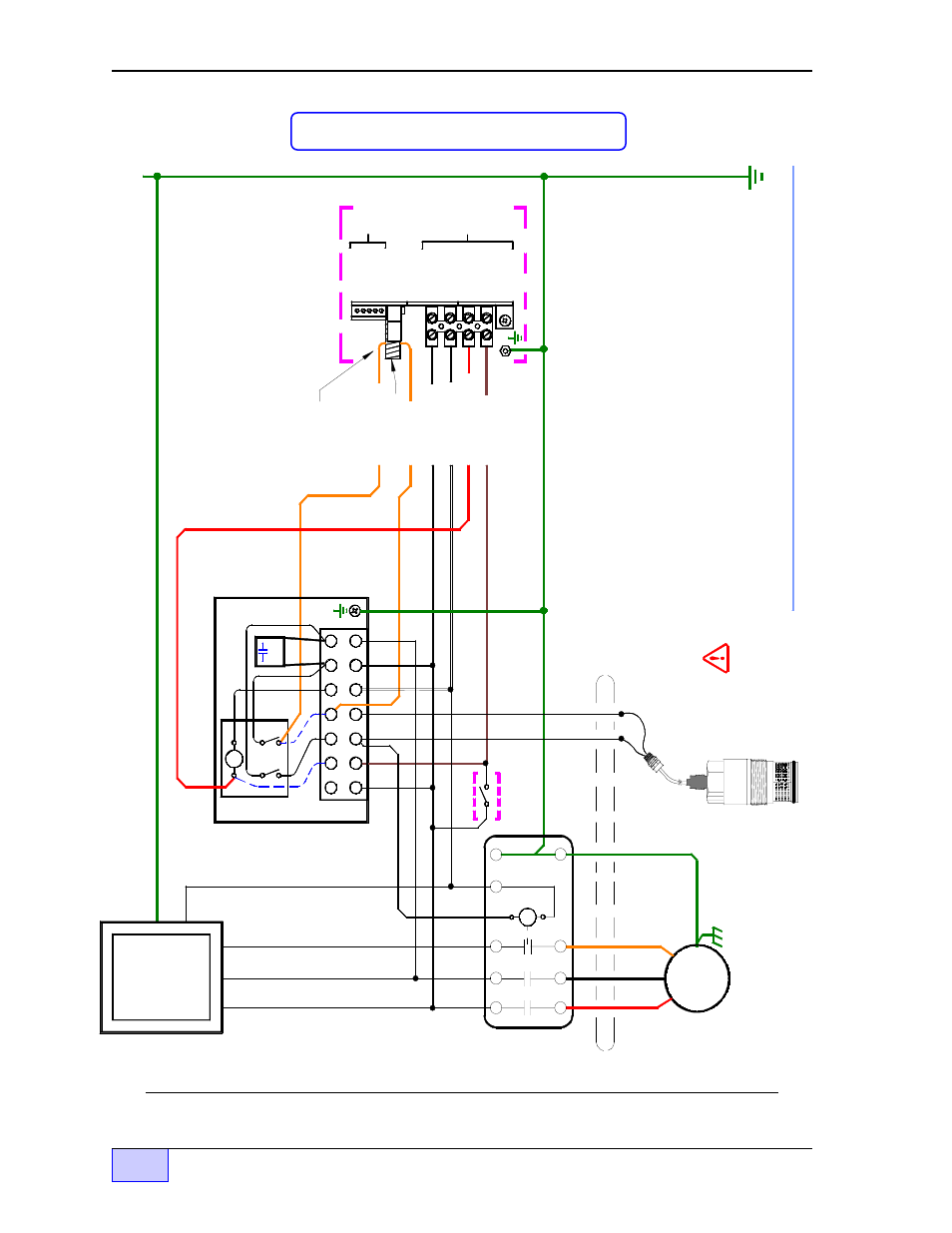
Figure 2.3-11 Three Phase 240 VAC Supply – Starter – and Motor Control Box
Standard Interface Schematic to TS-LLD
Install Line Filter Cap at L1 and L2
DANGER ELECTRICAL SHOCK HAZARDS. TURN OFF AND LOCK-OUT THE SUBMERSIBLE PUMP POWER SOURCE (L1, L2, L3 - AT THE CIRCUIT BREAKER) - BEFORE - WORKING ON THIS EQUIPMENT. FAILURE TO TURN OFF THE THREE PHASE POWER SOURCE WILL RESULT IN SEVERE INJURY OR DEATH.
Conduit to pump Junction Box
N
STP 3 phase Motor
...OverLoads
( OLs )
are in series with M1and M3
RED
BLK
ORG
Three Phase Motor Control Panel Starter ...see NOTES 1 and 2
T2
T1
T3
L1
L2
L3
TS-LLD LSU (Leak Sensing Unit) at IST Pump Housing Leak Detection Port
BLK
GND
GND
Dispense Switches
GND
L2
L1
L3
N
Electrical Power Panel
P/N
020-0028
S2
N (N o t e 1)
S1
M1
M2
NL
2
L1
Aux. Control Relay Box (remove dashed wires)
2 NEU
Neutral (WHT)
INCON TS-LLD & FE PETRO Three Phase STP Wirin
g Dia
gra
m
1) If the motor starter coil is 230 VAC then do not wire to neutral -- wire to M1.
2) Observe color code L1 L2 L3 phase sequence for proper rotation of motor.
3) All conduit fittin
gs, EYS seal fittin
gs, and junction boxes in
manholes or other Hazardous areas are to be explosionproof rated for: Class 1, Div 1, Group D and wet locations
NOTES
RLY COIL (RED)
S2 (BRN) Pump On Sig. (source = L1)
GND
TB1
4 P-IN
SIG RTN
3 P-OUT
TS-LLD Control Unit (CU)
Power Source = L1
No connection. Wire is routed through the donut-shaped Pickup Coil
Pickup Coil
L1 Line (BLK)
RLY N.O. (ORG)
M1 (ORG)
TB2
2 485B 3 DSY1
F1
4 DSY2 5 ALARM
1 110V
1 485A
GND