Figure 2.3-4 typical single phase 240 vac, Pump relay box & control unit wiring diagram - 5, Ts-lld control unit – Franklin Fueling Systems TS-LLD Installation Manual User Manual
Page 39: Pump relay box
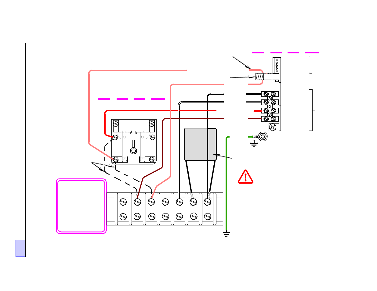
- - COM - -
N.O.
PUMP RELAY
F1
DANGER Electrical shock hazards!
Turn off and lock-out the submersible
pump power source (terminated at
L1 and L2), and the pump relay power
source (terminated at S2, from the
dispenser switch) BEFORE working
on this equipment. Failure to turn off
these power sources will result in
severe injury or death.
L2 (BLK)
M2 (ORG)
N (WHT)
TS-LLD Control Unit
RLY COIL (RED)
S2 (BRN)
GROUND
(GRN)
- - - COIL - - -
Install the 1uF Line Filter
Capacitor (INCON PN 020-0028)
Between L1 & L2
#8-32 Ground Stud
1 110V
2 NEU
3 P-OUT
TB2
1 485A
3 D S Y1
2 485B
5 ALAR M
4 D S Y2
SIG RTN
4 P-IN
TB1
Pickup Coil
Pump Relay Box
Remove wires
(shown as
dashed lines)
NOTE: Only the
new wiring
that's required
within the
Pump Relay
Box, is shown
in this diagram.
S1
M2
S2
M1 N
L2
L1
GROUND
STUD/SCREW
No termination - wire runs through
the donut-shaped Pickup Coil
RLY N.O. CONTACT (ORG)
- S940 (8 pages)
- Data Modem / Data Fax Modem for Tank Sentinel, AutoStik, & BulkStik ATGs (1 page)
- Tank Sentinel (TS-1001, 2001, 504, & 508) Setup Programming Guide (184 pages)
- Tank Sentinel (TS-1001, 2001, 504, 508 & 750) Setup Programming Guide (184 pages)
- Main System Board for Tank Sentinel, AutoStik, BulkStik ATGs (4 pages)
- TS-ROM2 (8 pages)
- Memory Backup Battery for Tank Sentinel, AutoStik, & BulkStik ATGs (2 pages)
- Tank Sentinel Quick Reference Guide (2 pages)
- Tank Sentinel (Except TS-2001), AutoStik Jr, BulkStik, AutoStik II (1-4 Ch) Display & Keypad Assembly (P/N 010-0087) (1 page)
- Tank Sentinel (TS-1001, 2001, 504, 508 & 750) Operators Guide Rev. D (100 pages)
- Tank Sentinel, AutoStik, BulkStik Printer Assembly (P/N 020-3050) (1 page)
- Tank Sentinel (TS-1001, 2001, 504, 508 & 750) Operators Guide Rev. C (100 pages)
- Tank Sentinel (TS-1001, 2001, 504, 508 & 750) Installation (98 pages)
- TS-1001, BulkStik, AutoStik (except AutoStik II 8Ch) Ribbon Cable (P/N 600-0077 & 600-0032) (1 page)
- TS-STS Sump Test System Kit (8 pages)
- TS-DTU Noise Suppression Cables TS-DRK (10 pages)
- Console DTU (Data Transfer Unit) (4 pages)
- TS-DTU Data Transfer Unit Dispenser Retrofit Manual (40 pages)
- Colibri One Pulse Relay Rule Setup (1 page)
- Colibri CL6 Installation Guide (12 pages)
- Colibri CL6 Setup and Operators Guide (32 pages)
- Colibri System Board Replacement (2 pages)
- Colibri Quick Reference (2 pages)
- Colibri: Connecting a T5 Series Fuel Management System or Colibri Tank Monitor to an ALVIC SCS3 Point of Sale System (3 pages)
- T5 Series Fuel Management System Installation Guide (30 pages)
- TS-550/TS-5000 consoles Secondary Containment Monitoring (28 pages)
- TS-550/TS-5000 Retrofit Printer Installation (1 page)
- T5 Series Fuel Management System Operators Guide (46 pages)
- T5 Series Fuel Management System Operators Guide (48 pages)
- T5 Series Fuel Management System Programming Guide (66 pages)
- T5 Series Fuel Management System Quick Reference Guide (2 pages)
- T5 Retrofit LCD Display Installation (1 page)
- T5 Tank Sentinel Programming Guide (48 pages)
- TSSP-TMPTR Thermal Printer (8 pages)
- TS 550 evo Fuel Management System Operators Guide (48 pages)
- TS 550 evo Fuel Management System Installation (28 pages)
- TS 550 evo Fuel Management System Quick Reference Guide (2 pages)
- TS 550 evo Fuel Management System Programming Guide (54 pages)
- TS-550 evo MODBUS Installation & Setup (22 pages)
- TS-LLD Changing the TS-LLD Control Unit (1 page)
- TS-LLD Changing the TS-LLD LSU Filter Screen or O-Ring (1 page)
- TS-LLD Leak Detection Sensor – Cleaning & BriteSensor Recovery (2 pages)
- TS-LLD Field Verification : Functional Testing of the INCON TS-LLD (2 pages)
- TS-LLD Changing the TS-LLD Control Unit Faceplate (1 page)
- TS-LLD Changing the TS-LLD 1 microfarad Line Filter Capacitor (1 page)