Final installation steps 2.3, Final installation steps - 14, Figure 2.3-13 control unit final assembly - 14 – Franklin Fueling Systems TS-LLD Installation Manual User Manual
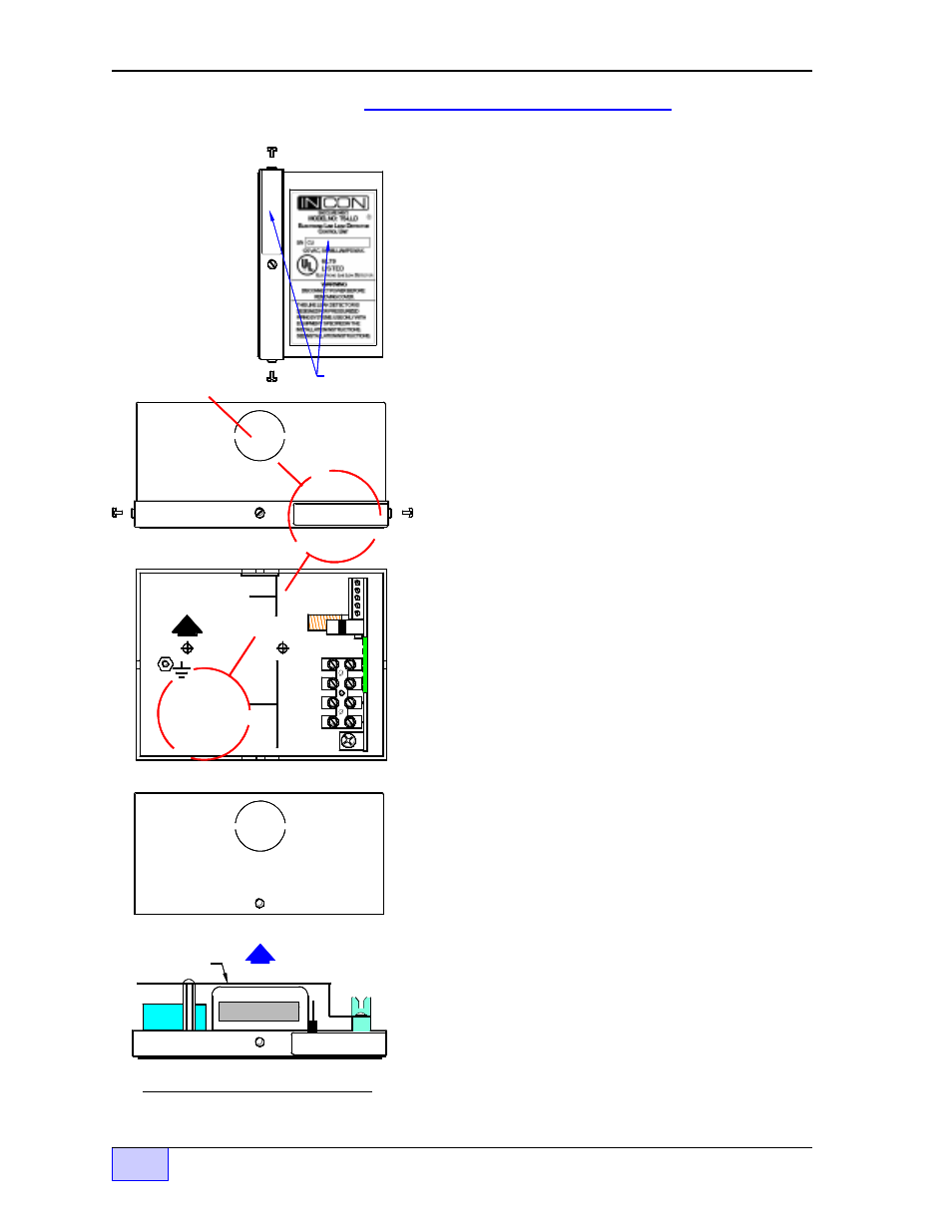
Page 48: Figure 2.3-13 control unit final assembly
Shield
1 485A
2 485B
3 DSY1
4 DSY2
5 ALARM
1 110V
2 NEU
3 P-OUT
TB1
4 P-IN
F1
UP
SIG RTN
TB2
INTERNAL VIEW
CU TOP VIEW
x x x x x x x
CU RIGHT SIDE VIEW
CU ENCLOSURE
TOP VIEW
KNOCKOUT
FOR 1/2 INCH
ELECTRICAL
FITTING
AT TOP &
BOTTOM
Line #:
Product:
Use a
perm anent
ink m arking
pen and
w rite the
Line #
Product:
on the
labels below .
For Exam ple
1
Gas
Line #:
Product:
1
Gas
LLD
# 1
Li
ne
# 1
Ga
so
lin
e
Line #:
Product:
TS
-LLD
C
U
S
er
ial
N
um
ber
x
x
x
x
x
x
x
x
C U S e ri a l
N u m b e r
Final Installation Steps
6)
Recheck your wiring. Make sure all terminations
are correct and tight.
7) Use a permanent ink marking pen to:
write the
Line # and the Product being monitored on two
CU labels — The label inside of the control unit,
and the label located on the top right of the cover
label (so the box and cover can be reinstalled as a
matched-set). See
Figure 2.3-6 to the left.
8)
Reinstall the correct CU cover on the box – as
a matched-set. See
Figure 2.3-6 to the left.
9)
Reinstall the pump relay box cover. See
Figures 2.3-1 & 2.3-3.
10) Nine
INCON Danger stickers are supplied with
each line leak detector (P/N 240-1175).
Apply
one sticker:
on the pump relay box cover, in
locations near dispenser fuel-line filters, plugs,
emergency safety-shut-off valves, on the TS-LLD
Leak Sensing Unit, and onto other serviceable
components of a fuel line (where a spill would
occur if the line became pressurized). The
selected surfaces must be clean, dry, and in plain
sight so that the warning can be read and followed.
Finally, see the next few Sections of this Chapter
about Optional Tank Gauge Console Interface and
the After Installation Steps / Testing.
— ❖ —