Control box – and bigflo pump (5 wire), Interface schematic to ts-lld - 11, Control unit installation page 2.3 - 11 – Franklin Fueling Systems TS-LLD Installation Manual User Manual
Page 45
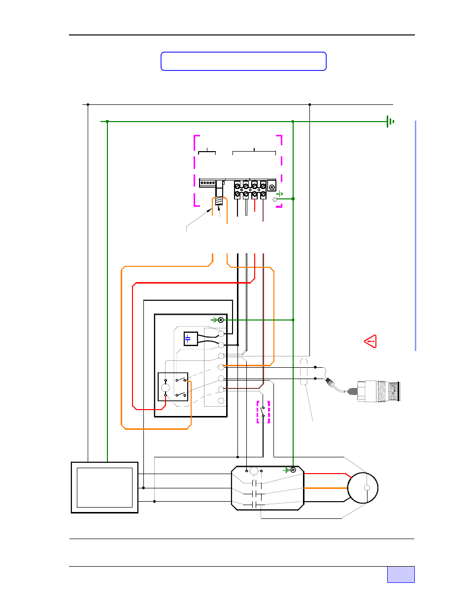
Figure 2.3-10 Three Phase 240 VAC Supply – Starter – Motor Control Box – and BigFlo Pump
INCON TS-LLD & RedJacket Big Flo Three Phase Wiring Diagram for older 5 wire Three Phase motors
DANGER ELECTRICAL SHOCK HAZARDS. TURN OFF AND LOCK-OUT THE SUBMERSIBLE PUMP POWER SOURCE (L1, L2, L3 - AT THE CIRCUIT BREAKER) - BEFORE - WORKING ON THIS EQUIPMENT. FAILURE TO TURN OFF THE THREE PHASE POWER SOURCE WILL RESULT IN SEVERE INJURY OR DEATH.
Three Phase Motor Starter (ref. Note 1)
N (N o t e 1)
Three Phase BigFlo STP... older version with separately wired
internal OverLoads ( OLs )
OL
RE
D
BLK
OR
G
T2
T1
T3
TS-LLD LSU (Leak Sensing Unit) at diaphragm valve
Separate wires must be run.
Dispense Switch
BLK
GND
L2
L1
L3
L1
L2
L3
Electrical Power Panel
N
Install Line Filter
Cap (between L1 and L2)
Aux. Control Relay Box (remove dashed wires)
S1
S2
M2
M1
L2
N
L1
P/N
020-0028
Neutral (WHT)
2 NEU
1) If the motor starter coil is 230 VAC then do not wire to neutral -- wire to M1. 2) Observe color code L1 L2 L3 phase sequence for proper rotation of motor. 3) All conduit fittings, EYS seal fittings, and junction boxes in manholes or other Hazardous areas are to be explosionproof rated for: Class 1, Div 1, Group D and wet locations
NOTES
RLY COIL (RED)
S2 (BRN) Pump On Si
g.
See Note 5
GND
4 P-IN
SIG RTN
3 P-OUT
TB1
TS-LLD Control Unit (CU)
Power Source = L1
F1
No connection. Run wire throu
gh the
donut-shaped Pickup Coil
L1 Line (BLK)
RLY N.O. (ORG)
M1 (ORG)
Pickup Coil
1 485A
3 DSY1
2 485B
4 DSY2 5 ALARM
1 110V
TB2
GND