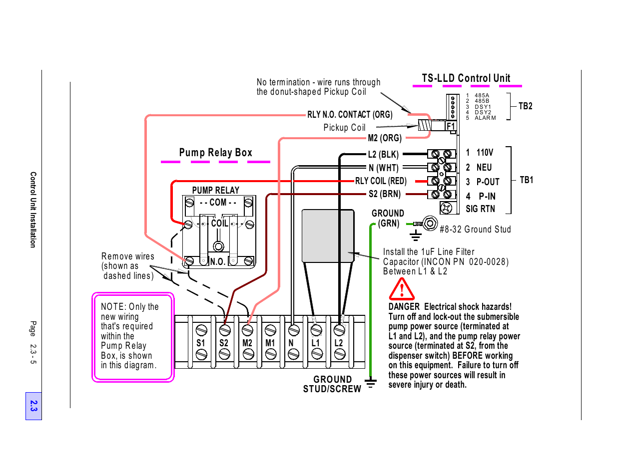
Figure 2.3-4 typical single phase 240 vac, Pump relay box & control unit wiring diagram - 5, Ts-lld control unit – Franklin Fueling Systems TS-LLD Installation Manual User Manual
Page 39: Pump relay box
See also other documents in the category Franklin Fueling Systems Equipment:
- S940 (8 pages)
- Data Modem / Data Fax Modem for Tank Sentinel, AutoStik, & BulkStik ATGs (1 page)
- Tank Sentinel (TS-1001, 2001, 504, & 508) Setup Programming Guide (184 pages)
- Tank Sentinel (TS-1001, 2001, 504, 508 & 750) Setup Programming Guide (184 pages)
- Main System Board for Tank Sentinel, AutoStik, BulkStik ATGs (4 pages)
- TS-ROM2 (8 pages)
- Memory Backup Battery for Tank Sentinel, AutoStik, & BulkStik ATGs (2 pages)
- Tank Sentinel Quick Reference Guide (2 pages)
- Tank Sentinel (Except TS-2001), AutoStik Jr, BulkStik, AutoStik II (1-4 Ch) Display & Keypad Assembly (P/N 010-0087) (1 page)
- Tank Sentinel (TS-1001, 2001, 504, 508 & 750) Operators Guide Rev. D (100 pages)
- Tank Sentinel, AutoStik, BulkStik Printer Assembly (P/N 020-3050) (1 page)
- Tank Sentinel (TS-1001, 2001, 504, 508 & 750) Operators Guide Rev. C (100 pages)
- Tank Sentinel (TS-1001, 2001, 504, 508 & 750) Installation (98 pages)
- TS-1001, BulkStik, AutoStik (except AutoStik II 8Ch) Ribbon Cable (P/N 600-0077 & 600-0032) (1 page)
- TS-STS Sump Test System Kit (8 pages)
- TS-DTU Noise Suppression Cables TS-DRK (10 pages)
- Console DTU (Data Transfer Unit) (4 pages)
- TS-DTU Data Transfer Unit Dispenser Retrofit Manual (40 pages)
- Colibri One Pulse Relay Rule Setup (1 page)
- Colibri CL6 Installation Guide (12 pages)
- Colibri CL6 Setup and Operators Guide (32 pages)
- Colibri System Board Replacement (2 pages)
- Colibri Quick Reference (2 pages)
- Colibri: Connecting a T5 Series Fuel Management System or Colibri Tank Monitor to an ALVIC SCS3 Point of Sale System (3 pages)
- T5 Series Fuel Management System Installation Guide (30 pages)
- TS-550/TS-5000 consoles Secondary Containment Monitoring (28 pages)
- TS-550/TS-5000 Retrofit Printer Installation (1 page)
- T5 Series Fuel Management System Operators Guide (46 pages)
- T5 Series Fuel Management System Operators Guide (48 pages)
- T5 Series Fuel Management System Programming Guide (66 pages)
- T5 Series Fuel Management System Quick Reference Guide (2 pages)
- T5 Retrofit LCD Display Installation (1 page)
- T5 Tank Sentinel Programming Guide (48 pages)
- TSSP-TMPTR Thermal Printer (8 pages)
- TS 550 evo Fuel Management System Operators Guide (48 pages)
- TS 550 evo Fuel Management System Installation (28 pages)
- TS 550 evo Fuel Management System Quick Reference Guide (2 pages)
- TS 550 evo Fuel Management System Programming Guide (54 pages)
- TS-550 evo MODBUS Installation & Setup (22 pages)
- TS-LLD Changing the TS-LLD Control Unit (1 page)
- TS-LLD Changing the TS-LLD LSU Filter Screen or O-Ring (1 page)
- TS-LLD Leak Detection Sensor – Cleaning & BriteSensor Recovery (2 pages)
- TS-LLD Field Verification : Functional Testing of the INCON TS-LLD (2 pages)
- TS-LLD Changing the TS-LLD Control Unit Faceplate (1 page)
- TS-LLD Changing the TS-LLD 1 microfarad Line Filter Capacitor (1 page)