Input configuration menu, Input configuration submenu adjustments, Input configuration menu – Extron Electronics MGP 462xi Series User Manual
Page 32: Input configuration submenu adjustments -10, Preliminar y, Operation, cont’d, Mgp series • operation 3-10, Input configuration menu flow
Operation, cont’d
MGP Series • Operation
3-10
PRELIMINAR
Y
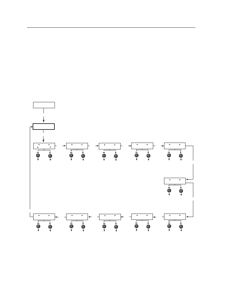
Input Configuration menu
The Input Configuration menu allows you to select a video signal type for each
of the four fully configurable inputs. All of these inputs can accept the following
video signals: RGB, YUV-HD, YUVi, RGBcvS, S-video, composite video, DVI
(MGP 464/462xi DI and HD-SDI only), and HD-SDI (MGP 464/462xi HD-SDI
only); RGB is the default. You can also select the horizontal and vertical start
positions, pixel sampling phase for the four windows (except for YUVi, S-video,
and composite video inputs), total pixels, active pixels, and active lines for each
input. Rotate the horizontal Adjust ([) knob to cycle through the four inputs, and
the vertical Adjust knob ({) to adjust the setting.
N
The 15 virtual inputs (numbered 5 through 19) cannot be configured from the
front panel; you must use SIS commands, the Windows-based control software,
or the MGP 464 or MGP 462xi Web pages.
Next
Next
Input #1
Film Mode ON
Next
Film Mode
Turn Film Mode on
or off (for low-
resolution devices).
Input
• Input #1
• Input #2
• Input #3
• Input #4
Input #1
RGB
Input video type
Select a signal format:
• RGB
• YUV-HD
• RGBcvS
• YUVi
• S-video
• Composite
• DVI (MGP 464 DI and
MGP 464 HD-SDI only)
• HD-SDI (MGP 464 HD-SDI only)
Input
• Input #1
• Input #2
• Input #3
• Input #4
Next
Input #1
Vert Start 0128
Next
Input
• Input #1
• Input #2
• Input #3
• Input #4
Vertical Start
Select a vertical
start line position
for the top edge of
the active video.
Input #1
Horz Start 0128
Input
• Input #1
• Input #2
• Input #3
• Input #4
Horizontal Start
Select a horizontal
start pixel position
for the left edge of
the active video.
Input
• Input #1
• Input #2
• Input #3
• Input #4
Input #1
PxPhs Win#1 16
Input
• Input #1
• Input #2
• Input #3
• Input #4
Pixel Phase 1
Adjust the pixel
sampling point
for window 1 for
each input.
Input #1
Total Pxl 1688
Input
• Input #1
• Input #2
• Input #3
• Input #4
Total Pixels
Specify the width in
pixels of the total
image area to be
sampled.
Next
Next
Input #1
Active Pxl 1280
Input
• Input #1
• Input #2
• Input #3
• Input #4
Active Pixels
Specify the width
in pixels of the
active image area
to be sampled.
Next
Input #1
Active Lns 1024
Input
• Input #1
• Input #2
• Input #3
• Input #4
Active Lines
Specify the height
in lines of the
active image area
to be sampled.
Next
Next
Input #1
PxPhs Win#2 16
Input
• Input #1
• Input #2
• Input #3
• Input #4
Pixel Phase 2
Adjust the pixel
sampling point
for window 2 for
each input.
Input
Configuration
Menu
Auto
Image
Input #1
PxPhs Win#3 16
Input
• Input #1
• Input #2
• Input #3
• Input #4
Pixel Phase 3
Adjust the pixel
sampling point for
window 3 for each
input.
Input #1
PxPhs Win#4 16
Input
• Input #1
• Input #2
• Input #3
• Input #4
Pixel Phase 4
Adjust the pixel
sampling point for
window 4 for each
input.
Next
Next
Input Configuration menu flow
Input configuration submenu adjustments
The table on the next page shows how to make the selections and adjustments that
are accessed through the Input Configuration submenus.