Extron Electronics DMP 44 LC Setup Guide User Manual
Dmp 44 lc • setup guide, Rear panel features and connections a, Installing the dmp 44 lc
IMPO
RTAN
T:
Go to www
.extron.com f
or the
complete user guide
, installation
instructions,
and specifications.
DMP 44 LC • Setup Guide
The Extron DMP 44 LC Digital Matrix Processor is a compact 4x4 audio matrix processor featuring a digital signal processing
(DSP) platform for audio signal routing, processing, and control. The DMP 44 LC features four line level inputs and outputs, all
balanced or unbalanced. It offers several audio DSP tools for mixing, routing, and room optimization with quick and intuitive
configuration using the DSP Configurator™ Software.
NOTE:
For full installation, configuration, and operation details, see the DMP 44 LC User Guide available at
.
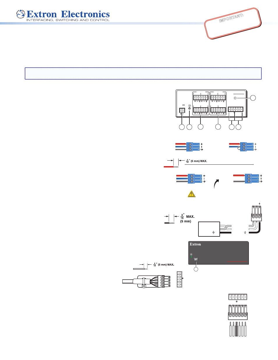
Rear Panel Features and Connections
a
12 VDC power connector
e
RS-232 connector
b
Power/Reset LED
f
Digital input connector
c
Line input connectors (1 – 4)
g
Reset button
d
Line output connectors (1 – 4)
Installing the DMP 44 LC
1.
Disconnect power from all equipment.
2.
(Optional)
Mount the unit to a rack or furniture.
3.
Connect the audio input. Connect up to four balanced or
unbalanced mono line level input devices to line input
connectors
c
above (see the wiring diagram on the right).
4.
Connect the audio output. For balanced or unbalanced
audio output, connect up to four output devices to line output
connectors
d
above (see the wiring diagram on the right).
5.
Connect a control device. Connect a host device, such as a
computer, to one of the following DMP 44 LC ports to
configure and control the DMP via Simple Instruction Set (SIS™)
commands.
•
RS-232 port (rear panel) — Connect a host device to the
Tx, Rx, and
_
(ground) pins of this 6-pole captive screw
connector (
e
). The default baud rate for this port is 38400 baud,
1 stop bit, no parity, 8 data bits, and no flow control (see the
wiring diagram on the right).
•
Config port (front panel) — Connect a USB cable (USB-A to
Mini-B) between a USB port on your computer and this
port (
a
on the front panel illustration shown on the right).
Digital input connector. Up to three
configurable input ports (see
f
on the
rear panel diagram) allow connection
to various digital devices including
motion detectors, alarms, buttons,
photo (light) sensors, and temperature
sensors. This connector shares a
ground pin with the RS-232 connector (see the wiring diagram above). Both the RS-232
and digital input connectors may be used simultaneously by using a 6-pin captive screw
connector with two wires sharing the same ground connector (see the diagram on the right).
6.
Reset button. The recessed reset button is used to access various modes of resets. The
green power LEDs on both the front and rear panels indicate the reset mode that was accessed.
The reset modes are detailed in the user guide.
7.
Connect power to the DMP 44 LC by connecting the included 12 VDC external power supply
to the rear panel power connector (see
a
in the rear panel diagram). The wiring diagram is
shown on the right.
Balanced
Unbalanced
Tip
Ring
Sleeve
Tip
Sleeve
Receive (Rx)
Transmit (Tx)
Ground ( )
Bidirectional
RS-232
Device
Ground ( )
Receive (Rx)
Transmit (Tx)
Rx
Tx
Do not tin
the wires!
DMP 44 LC
RESET
Tx Rx 1 2 3
RS-232 DIGI IN
3
4
1
2
3
4
1
INPUTS
2
OUTPUTS
POWER
12V
0.3A MAX
7
1
2
3
4
5
6
DMP 44 LC
DIGITAL MATRIX PROCESSOR
CONFIG
1
Audio Output Wiring
CAUTION
For unbalanced audio, connect the
sleeve to the ground contact.
DO NOT
connect the sleeve to the
negative (−) contacts.
Unbalanced Output
Tip
Sleeve
NO Ground Here
Balanced Output
Tip
Sleeve
Ring
Audio Input Wiring
Balanced Input
Tip
Sleeve
Ring
Tip
Sleeve
Unbalanced Input
RS-232
DIGI IN
Tx Rx 1 2 3
Do not tin the wires!
1
2
3
_
RS-232
2
1
Tx
Rx
DIGI IN
3