Extron Electronics Annotator and USP 507 Output Boards User Manual
Installing a board in the annotator or usp 507, At the rear optional output slot either, Remove the two securing screws
The Extron Annotator and
USP 507 have a series of
optional output boards.
These boards are:
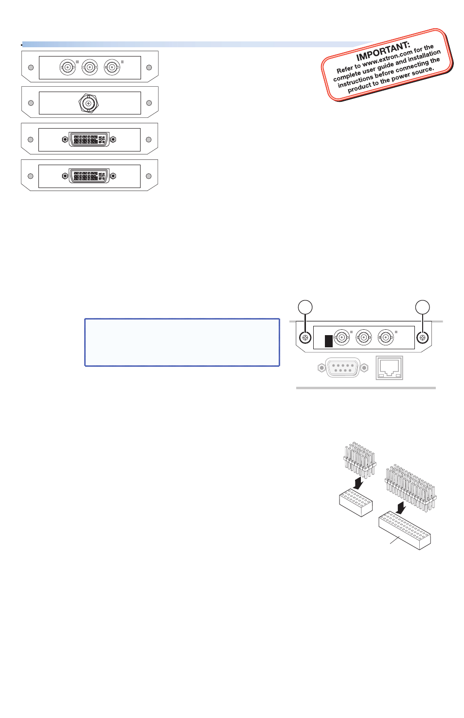
• Scan converter board • 3G/HD-SDI board • DVI-D board •
Scaler board (with DVI-I). Any one of these boards mounts
in the optional output slot, above the RGB and MTP ports,
at the rear of the Annotator or USP 507.
For full device operating details, refer to either the
Annotator User Guide or the USP 507 User Guide, both
available at
Annotator and USP 507
Optional Output Boards • Installation Guide
Continued on side 2.
1
3G/HDSDI
OUT
DVI-D
OUT
LO-
RES
OUT
R-Y/
R
C
Y/
G
VID
B-Y/
B
Y
SCALED
DVI-I
OUT
Installing a Board in the Annotator or USP 507
1.
Turn off the unit, and remove the power cord. Repeat for all connected devices.
2.
Remove eight cover-securing screws from the top and three from each side. Slide
the top cover off. Retain the 14 screws.
3.
At the rear optional output slot either:
a.
Remove the two securing screws
a
from either side of the blank plate and lift
the plate away. Retain the screws.
NOTE:
Re-use the screws to secure
the new output board in
place. Retain the blank plate.
Or,
b.
If a board is already installed in the output slot, remove any cables and the two
screws
a
. Then remove the retaining screw that secures it to the post on the
device motherboard. Carefully lift the board away from the socket. Retain all
the screws.
4.
Remove the new board from its box and anti-ESD bag,
holding the board by the front frame or board edge.
5.
Turn the board over so the header sockets face up.
Insert the supplied connector pins into all sockets on
the board. Depending on the option card being
installed, the second header may not be present.
6.
Turn the board over again so the connector pins are now
facing down. Carefully align the pins with the appropriate
sockets on the unit motherboard, and push the board firmly down into the sockets.
7.
Secure the board to the frame with the two retaining screws
a
and to the post on
the motherboard using either the original or the supplied screw.
8.
Replace the cover, securing it with the fourteen screws removed in step 2.
9.
Reconnect any input and output devices and connect to the new board.
10.
Connect any control devices.
11.
Power on the Annotator or USP 507, and all the connected devices.
2
Header Socket
1
RGB/R-Y,Y,B-Y
MTP
LO-
RES
OUT
R-Y/
R
C
Y/
G
VID
B-Y/
B
Y
1
1