Figure 6-8: blj3 dip switch settings when using a, Vectorcontroller, Blj3 to blj3 (vector controller), continued – GE Industrial Solutions Galaxy Power Systems User Manual
Page 82
Installation Guide for Galaxy Power Systems
6 - 14 Centralized or Distributed Architecture Connections
Issue 12 August 2012
Intercabinet Alarm and Serial Bus Connections, continued
BLJ3 to BLJ3
(Vector Controller),
continued
BLJ3 to BLJ3 (Vector Controller), continued
Step
Action
5
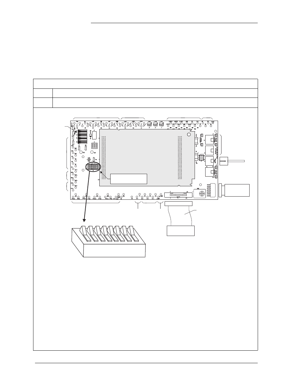
Set the DIP switch on the BLJ3 board. (Factory default for DIP switches is 0.)
Alarm Outputs
Fuses
Contactors
Alarm Inputs
Thermal Inputs
Plant Voltage
Regulation Input
Bay
Alarm Out
Unused
Unused
Unused
Unused
To Modem/
Gateway/
Local Terminal
Front Panel
Control/Display
To Rectifiers
Power In/Out
Shunts 1 and 2
Unused
Vector Controller
Board Not Shown
26 Conductor
Ribbon Cable
Vector Controller Board
(GCM2, GCM3)
System Configuration
DIP Switches
0
1
1
S1
2
3 4
5
6 7
8
S1.2: Software Mode
1,2
S1.3: Option Card Availability
S1.5: Alarm Contact Select
1
S1.7: Power Battery Test
S1.1: Front Panel Configuration
0
1
0
1
0
1
0
1
0
1
- Enabled (shown)
- Disabled
- Standard (shown)
- Flexent System Only
- Modem
- Galaxy Gateway Card (Internet)
S1.4: Rectifier Class
0
1
- Standard GPS Rectifiers
- NP Rectifiers
- Standard HV, High Voltage
- VLV, Very Low Voltage
- Disabled (shown)
- Active
S1.6: - Set to 0
S1.8: - Set to 0
1. Setting both SW1.2 and SW1.5 to "1" will result in activating the HV alarm cont act.
2. SW1.2 setting will only be read by the software when the GCM is powered up.
Figure 6-8: BLJ3 DIP Switch Settings When Using a
VectorController