Connector x2 – R&M Materials Handling HOIST MONITORS User Manual
Page 9
R&M Materials Handling, Inc.
4501 Gateway Boulevard
Springfield, Ohio 45502
P.: (937) 328-5100
FAX: (937) 325-5319
9/105
R&M Materials Handling, Inc. reserves the right to alter or amend the above information without notice.
Connector X2:
Terminal
Signal
Description
20
PE
Protective earth
21
TP11
22
TP12
Thermistor input 1
23
TP21
24
TP22
Thermistor input 2
25
10V
Load sensor supply, 10...12 VDC
26
AIN1
Analogue input 1
27
AIN2
Analogue input 2
28
AIN3
Analogue input 3
29
IB
Current transformer common
30
0V
Load sensor supply, 0 V
31
-
Not used
32
CL-A
33
CL-B
Current loop for display
34
AN
Analogue output
35
AN0
Analogue output, ground
36
CAN-H
CAN bus, high
37
CAN-L
CAN bus, low
38
CAN-GD
CAN bus, neutral
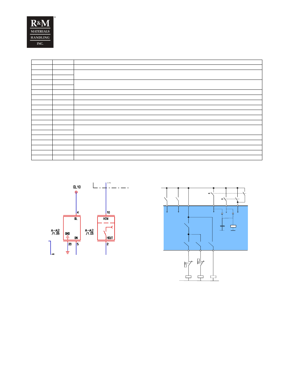
Input request is not directly connected to the output. Output voltage comes from Control
Voltage Line (OL) (via Safety Relay and Control relay). See simplified pictures.
R H
R L
R F
H O U T
LO U T
FO UT
O L
R S
HIN
LIN
FIN
M FI1
M F I2
R S
A -K 1
A -K 2
U P
D O W N
A -K 4
C ontrol voltag e
F AS T
Connections on eldrawings
Unit’s internal connections