4 parameters – R&M Materials Handling HOIST MONITORS User Manual
Page 18
R&M Materials Handling, Inc.
4501 Gateway Boulevard
Springfield, Ohio 45502
P.: (937) 328-5100
FAX: (937) 325-5319
18/105
R&M Materials Handling, Inc. reserves the right to alter or amend the above information without notice.
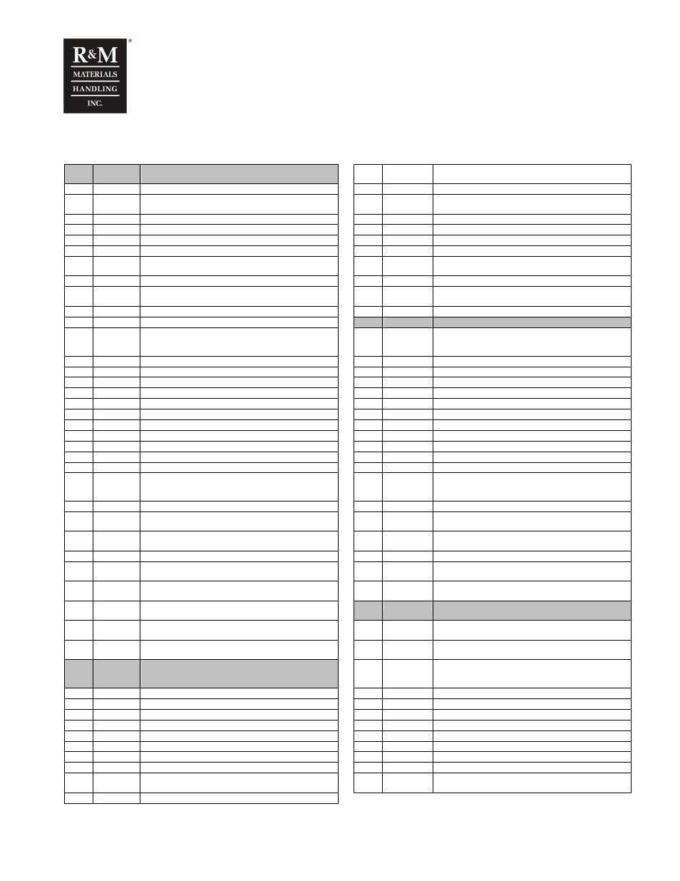
4 Parameters
1
Monitor 1
Read only menu for condition monitoring values and
measured values.
2-11
Over ED
Counts the minutes when ED value has exceed the
nominal ED value
1-1
Cond mon Condition monitoring menu
2-12
SWPRT%
SWP% value calculated with hoist running time
1-1-1
SWP%
Remaining Safe Working Period of the hoist in
percentage, starting from 100%.
2-13
SRT3
Load sum with hoist running time, third power
1-1-2
Starts
Total number of starts
2-14
SRT8
Load sum with hoist running time, eight power
1-1-3
Run time
Total running time
2-15
SWPHC%
SWP% value calculated with hoist cycles
1-1-4
Cycles
Total number of hoisting cycles.
2-16
SL1
Load sum with hoist cycles, the first power (mean load)
1-1-5
Mean load
Average of the handled load
2-17
SL3
Load sum with hoist cycles, the third
1-1-6
Br SWP%
Remaining Safe Working Period of the brake in
percentage.
2-18
SL8
Load sum with hoist cycles, the eight power
1-1-7
MFI1 RT
Total hours of running time, when MFI1 input is closed.
2-19
Power on
The total power on time of the unit
1-1-8
MFI1 ST
Total amount of starts, when MFI1 input is closed.
2-20
Temp Index
Power on time of the unit, weighted with the unit’s
temperature
1-1-9
MFI2 RT
Total hours of running time, when MFI2 input is closed.
2-21
Max load
Maximum measured value of the load
1-1-10 MFI2 ST
Total amount of starts, when MFI2 input is closed.
3
Load setup Load calibration menu. Accessible password level 2
1-2
Measure
Measurement menu
3-1
Cal. Motor
Load calibration when the motor torque based load
measurement is selecte. See chapter “Load
calibration sequence with motor torque”.
1-2-1
Act. Load
The measured actual load value.
3-2
MC values
Load calibration values for the motor torque method
1-2-2
Temp 1
Temperature measured at thermistor input 1.
3-2-1
Load 1
The higher test load’s value
1-2-3
Temp 2
Temperature measured at thermistor input 2.
3-2-2
Mhs1
Motor torque for hoisting in slow speed, with load.
1-2-4
Supply L1
Line voltage of phase L1.
3-2-3
Mhf1
Motor torque for hoisting in fast speed, with load 1.
1-2-5
Supply L2
Line voltage of phase L2.
3-2-4
Mls1
Motor torque for lowering in slow speed, with load 1.
1-2-6
Supply L3
Line voltage of phase L3.
3-2-5
Mlf1
Motor torque for lowering in fast speed, with load 1,
1-2-7
Motor I1
Motor current of phase L1.
3-2-6
Load 2
The lower test load’s value.
1-2-8
Motor I2
Motor current of phase L2.
3-2-7
Mhs2
Motor torque for hoisting in slow speed, with load 2.
1-2-9
Motor I3
Motor current of phase L3.
3-2-8
Mhf2
Motor torque for hoisting in fast speed, with load 2.
1-2-10 Ain1 value
Measured voltage at analogue input AIN1.
3-2-9
Mls2
Motor torque for lowering in slow speed, with load 2.
1-2-11 Ain2 value
Measured voltage at analogue input AIN2.
3-2-10 Mlf2
Motor torque for lowering in fast speed, with load 2.
1-2-12 Ain3 value
Measured voltage at analogue input AIN3.
3-3
Cal. Sens
Load calibration when the sensor based load
measurement is selected. See chapter “Load
calibration sequence with the load sensor”.
1-2-13 Int. temp
Internal temperature of the unit.
3-4
SC values
Load calibration values for the load sensor method
1-2-14 Input
Indicates the status of the inputs: HIN, LIN, FIN, MFI1 &
MFI2.
3-4-1
Load 1
The higher test load value.
1-2-15 Output
Indicates the status of the outputs: HOUT, LOUT,
FOUT, RS & ROUT.
3-4-2
Input 1
The load measurement voltage in the analogue input
Ain1 corresponding to the higher test load
1-2-16 Supply f
Supply voltage frequency (50 or 60Hz)
3-4-3
Load 2
The lower test load value
1-3
Min/Max
Minimum / maximum value menu
3-4-4
Input 2
The load measurement voltage in the analogue input
Ain1 corresponding to the lower load
1-3-1
Min supply
Minimum measured value of the supply line voltage
RMS.
3-5
OL protect
Set to “OFF” to temporarily by-pass of the overload
protection
1-3-2
Max supply Maximum measured value of the supply line voltage
RMS.
4
Start-up
Start- menu. Accessible password level 4
1-3-3
Min Int. T
Minimum measured value of the internal temperature of
the unit.
4-1
MFI1
Multi-Functional Input 1 parameters
1-3-4
Max Int. T
Maximum measured value of the internal temperature of
the unit.
4-1-1
MFI1 oper.
Selects the function of MFI1:
2
Monitor 2
Read only menu for advanced condition monitoring
values and measured values. Accessible password
level 3
4-1-2
MFI1 IntL
Intermediate load limit value
2-1
SW version Software version of the unit
4-1-3
MFI1 2OLL
The second load
2-2
RT slow
Total run-time in slow speed
4-1-4
MFI1 CintL
Bridge intermediate load limit value.
2-3
RT fast
Total run-time in fast speed
4-2
MFI2
Multi-Functional Input 2 parameters
2-4
No. OT
Total number of hoist motor overtemperature incidents.
4-2-1
MFI2 oper.
Selects the function of MFI2:
2-5
No. OL
Total number of overload incidents
4-2-2
MFI2 IntL
The (second) intermediate load limit value
2-6
E-stops
Total number of emergency stops incidents
4-2-3
1+2 IntL
The third intermediate load limit value
2-7
ST up
Total number of starts in up direction
4-2-4
MFI2 2OLL
The second load limit
2-8
ST down
Total number of starts in down direction
4-2-5
MFI2 CintL
The (second) bridge intermediate load limit value
2-9
ST fast
Total number of starts to fast speed (counts in two
speed control only)
4-2-6
1+2 CintL
The third bridge intermediate load limit value
2-10
Max ED
Maximum value of the calculated ED percentage