R&M Materials Handling HOIST MONITORS User Manual
Page 75
R&M Materials Handling, Inc.
4501 Gateway Boulevard
Springfield, Ohio 45502
P.: (937) 328-5100
FAX: (937) 325-5319
75/105
R&M Materials Handling, Inc. reserves the right to alter or amend the above information without notice.
14.3 Blank display
•
If display shows “blank”, check that display location selection switch
position is right, logal (LOC) or remote (REM), in the monitoring unit.
•
Check the connections from the unit to the display
•
Change the remote display cables connections for terminals 32 and 33
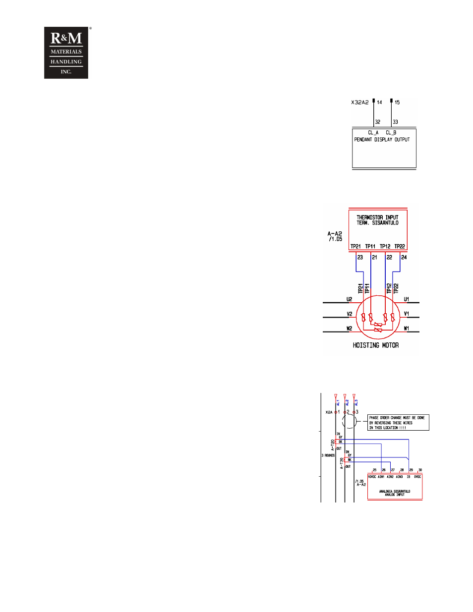
14.4 The temperature sensors (NTC-wiring)
If the NTC-sensor is selected and the temperature sensor is not
connected, the values for parameters 1-2-2 “Temp 1” and/or
parameter 1-2-3 T2 are about -50
o
C.
Check that temperature sensor 1 (slow speed) is connected across
terminal 21 and 22 and that the slow speed temperature is
measured with channel T1 (parameter 4-7-6 is set to “T1”)
When driving in slow speed, the value of parameters 1-2-2 “Temp 1”
should increase.
Check that temperature sensor 2 (fast speed) is connected across
terminal 23 and 24 and that the fast speed temperature is measured
with channel T2 (parameter 4-7-7 is set to “T2”).
When driving in fast speed, the value of parameters 1-2-3 “Temp 2”
should increase.
Reverse the connections of terminals 21-22 and 23-24 when
needed, and carry out the calibration procedure again.
14.5 Current transformers
•
Check that the current transformer AT-20 is connected across
terminals 26 and 29
•
Check that the current transformer AT-30 is connected across
terminals 27 and 29
•
The grey wires of both transformers must be connected to
terminal 29.
If one of current transformers is connected wrong, it can be checked
with parameters 1-2-9 “Motor I3”. In that case, parameter 1-2-9 has
a different value than parameters 1-2-7 “Motor I1” and parameter 1-
2-8 “Motor I2”, whereas all three should have the same value. The
most common fault is that the input wire goes trough the
transformers in the wrong direction.