5 service menu (menu 5), 6 design values menu (menu 6) – R&M Materials Handling HOIST MONITORS User Manual
Page 88
R&M Materials Handling, Inc.
4501 Gateway Boulevard
Springfield, Ohio 45502
P.: (937) 328-5100
FAX: (937) 325-5319
88/105
R&M Materials Handling, Inc. reserves the right to alter or amend the above information without notice.
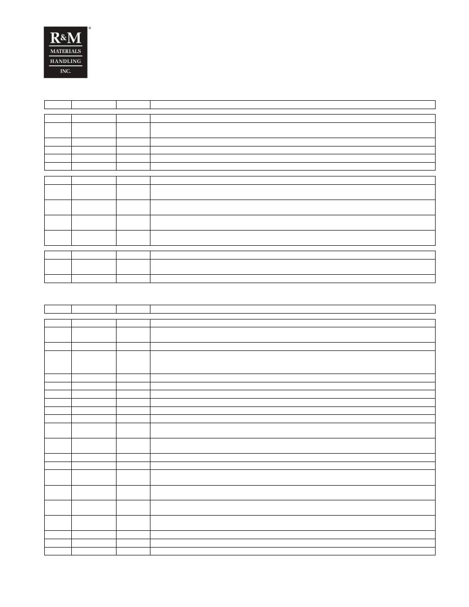
16.5 Service menu (Menu 5)
5
Service
Start- menu. Accessible password level 5
Param. Name
Value
Description
5-1
S limits
The limit values to indicate the need for service. A service warning is displayed in case one of
the values exceeds the given limit.
5-1-1
S Run time
“nnnn” h
Run time service limit
5-1-2
S starts
“nnnnn”
Service limit for the number of starts
5-1-3
S SWP%
“nn” %
Service limit for SWP%
5-1-4
S Br SWP%
“nn” %
Service limit for the hoist brake service life
Param. Name
Value
Description
5-2
Fault log
“n”
The logger for the latest fault situations, the number “n” indicates the number of faults in the
logger
5-2-1
F_”XXX”
“nnnnn”
The latest fault. The fault code “XXX” and the actual number of starts “nnnnn” at the moment when the
fault was detected. Refer to chapter “Faults” for the fault descriptions
5-2-2
F_”XXX”
“nnnnn”
The second latest fault. The fault code “XXX” and the actual number of starts “nnnnn” at the moment
when the fault was detected. Refer to chapter “Faults” for the fault descriptions
5-2-“n”
F_”XXX”
“nnnnn”
The “n” latest fault (highest number is 30). The fault code “XXX” and the actual number of starts “nnnnn”
at the moment when the fault was detected. Refer to chapter “Faults” for the fault descriptions
Param. Name
Value
Description
5-3
Reset log
“n”
Resets the fault log by pushing the ENT button. The number “n” indicates the amount of faults
presently in the logger.
5-3
Reset log ?
The reset action must be confirmed by pushing the ENT button once more
16.6 Design values menu (Menu 6)
6
Design
Design values menu. Accessible password level 6
Param. Name
Value
Description
6-1
Hoist name
“X”
Identifying letter of the hoist-monitoring unit, A, B, C, D or E. Each connected unit in a multi-hoist
application, connected via the CAN-bus must have a unique letter.
6-2
Unit No
“nnnnn”
The serial number of the hoist. Setting is informative only, there is no function behind the value.
6-3
Class
“n”
Mechanical class for the hoist according to the FEM / ISO duty classes. See chapter
“Primary monitoring items” of this manual for details. Setting is informative only, there is no function
behind the value.
6-4
Nom. Load
“nn.n” t
Rated load of the single hoist connected to the unit
6-5
Nominal ED
“nn” %
Rated ED value of the hoist
6-6
Sp ratio
“n”
Speed ratio. Two-speed systems: slow-fast (i.e. 6), inverter drives: always 1
6-7
Max ST
“nnnnn”
Maximum allowed number of starts
6-8
Max E-stop
“nnnnn”
Maximum allowed number of interrupted hoists (emergency stops)
6-9
Max RT
“nnnn” h
Maximum allowed run-time in hours
6-10
D SRT3
“nnnnn”
Designed running hours, power three. Equals the safe working period in hours as described in chapter
“Primary monitoring items” of this manual.
6-11
D SRT8
“nnnnn”
Designed running hours, power eight. Equals the safe working period in hours as described in chapter
“Primary monitoring items” of this manual.
6-12
D SL3
“nnnnn”
Design constraint for hoisting cycles, power three
6-13
D SL8
“nnnnn”
Design constraint for hoisting cycles, power eight
6-14
MaxST MFI1
“nnnnn”
Max number of MFI1 starts. See chapter “Run time and start counter for trolley and bridge” for
details
6-15
MaxRT MFI1
“nnnn” h
Max running time for MFI1. See chapter “Run time and start counter for trolley and bridge” for
details
6-16
MaxST MFI2
“nnnnn”
Max number of MFI2 starts. See chapter “Run time and start counter for trolley and bridge” for
details
6-17
MaxRT MFI2
“nnnn” h
Max running time for MFI2. See chapter “Run time and start counter for trolley and bridge” for
details
6-18
Max Br
“nnnnn”
Max number of braking actions, for calculating the brake’s life-time
6-19
Max Control
“nnnnn”
Max number of Control, for calculating the contactors’ life-time
6-20
Password
“nnnn”
Set password level 1 (4digits). Customer password or device related password.