R&M Materials Handling HOIST MONITORS User Manual
Page 62
R&M Materials Handling, Inc.
4501 Gateway Boulevard
Springfield, Ohio 45502
P.: (937) 328-5100
FAX: (937) 325-5319
62/105
R&M Materials Handling, Inc. reserves the right to alter or amend the above information without notice.
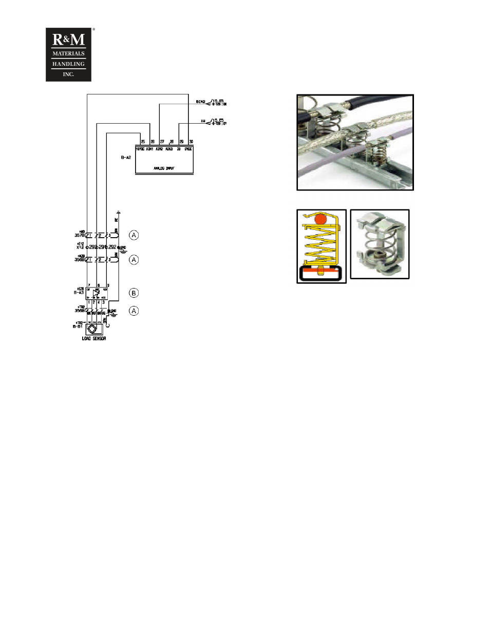
A. Shield is grounded with 360 degree connector
B. Amplifier KAE400
12.1.4 Adjustment
Tools needed for adjustment:
•
A small screwdriver for trimmers
•
Test load
Adjustment can be done with a known load in the range of 80…130% of the rated lifting capacity.
Following procedure can be used to perform the setup of the amplifier:
•
Connect the sensor and monitoring unit. In a case of half bridge sensor the signal is connected to
+IN-terminal. Connect the cable shields outside of the amplifier to 360° terminals.
•
Select the sensor type, full bridge (1/1) or half bridge (1/2) by the dipswitch.
•
Set the gain to 400 by the dipswitch
•
Switch the power on
•
If amplifier and monitoring unit are near each other, go to the monitoring unit parameter 1-2-10 Ain 1.
The parameter 1-2-10 shows amplifiers output signal level. If the monitoring unit’s display can’t be
read a multimeter is needed. Measure voltage level between KAE400’s terminal 6 and 7.
•
Set the zero at no load by turning the trimmer until the led lits and then slightly back that the led does
not lit anymore. Led lits when the output is below 2,1VDC.
•
Check the gain at higher nominal load. If the output is over 6,5VDC set the gain to 160 by the
dipswitch. If the output is under 2,0VDC exchange the wires –S and +S, and return back to section 5.
•
Perform the calibration of the monitoring unit at nominal load and at no load