2 intermediate load limits connections – R&M Materials Handling HOIST MONITORS User Manual
Page 36
R&M Materials Handling, Inc.
4501 Gateway Boulevard
Springfield, Ohio 45502
P.: (937) 328-5100
FAX: (937) 325-5319
36/105
R&M Materials Handling, Inc. reserves the right to alter or amend the above information without notice.
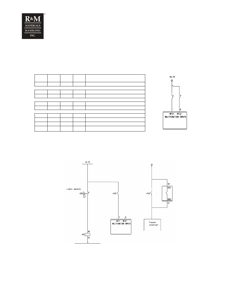
7.3.2 Intermediate load limits connections
One or two “normally closed” contact should be connected to the multi-functional inputs. The contacts
can either be manual switches, or automatically actuated according to the position of the crane.
The intermediate load function operates according to the following logic:
MFI1
oper.
MFI2
Oper
MFI1
status
MFI2
status
Active load limit
NU
NU
-
-
Normal Overload limit
IntL
NU
ON
-
Normal Overload limit
IntL
NU
OFF
-
MFI1 load limit. The parameter 4-1-2
NU
IntL
-
ON
Normal Overload limit
NU
IntL
-
OFF
MFI2 load limit, The parameter 4-2-2
IntL
IntL
ON
ON
Normal Overload limit
IntL
IntL
ON
OFF
MFI1 load limit. The parameter 4-1-2
IntL
IntL
OFF
ON
MFI2 load limit. The parameter 4-2-2
IntL
IntL
OFF
OFF
MFI1+2 load limit. The parameter 4-2-3
The hoist-monitoring unit will prevent the hoisting motion when the measured load exceeds 110%
of the intermediate load for a period of time. The overload protection is reset when the measured
load decreases to 80% of the intermediate load.
Connections if this function is used to do a load limited area
7.4 Run time and start counter for trolley and bridge
In addition to the hoist run-time and starts counter, the hoist-monitoring unit can be programmed to count
the total run-time and starts of either the trolley and/or bridge travel motion. When this option is activated,
a complete overview of the usage of the crane is recorded.