6 state transition timing summary, Rs to – Rainbow Electronics AT86RF231 User Manual
Page 42
42
8111A–AVR–05/08
AT86RF231
/RST = L sets all registers to their default values. Exceptions are register bits CLKM_CTRL (reg-
ister 0x03, TRX_CTRL_0), refer to
Section 9.6.4 “Master Clock Signal Output (CLKM)” on page
.
After releasing the reset pin (/RST = H) the wake-up sequence including an FTN calibration
cycle is performed, refer to
Section 9.8 “Automatic Filter Tuning (FTN)” on page 125
. After that
the TRX_OFF state is entered.
illustrates the reset procedure once the P_ON state was left and the radio
transceiver was not in SLEEP state.
The reset procedure is identical for all originating radio transceiver states except of state P_ON
and SLEEP state. Instead, here the procedure described in
Section 7.1.2.1 “P_ON - Power-On
must be followed to enter the TRX_OFF state.
If the radio transceiver was in SLEEP state, the XOSC and DVREG are enabled before entering
TRX_OFF state.
If register TRX_STATUS indicates STATE_TRANSITION_IN_PROGRESS during system initial-
ization until the AT86RF231 reaches TRX_OFF, do not try to initiate a further state change while
the radio transceiver is in this state.
Notes
• The reset impulse should have a minimum length t
10
= 625 ns as specified in
“Digital Interface Timing Characteristics” on page 157
, see parameter 12.4.13.
• An access to the device should not occur earlier than t
11
≥ 625 ns after releasing the pin
Section 12.4 “Digital Interface Timing Characteristics” on page 157
, parameter
12.4.14.
• A reset overrides an SPI command request that might be queued.
7.1.4.6
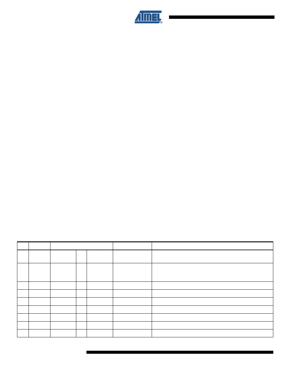
State Transition Timing Summary
The transition numbers correspond to
and do not include SPI access time
if not otherwise stated. See measurement setup in
Table 7-1.
State Transition Timing
No
Symbol
Transition
Time [µs], (type)
Comments
1
t
TR1
P_ON
until CLKM
available
380
Depends on external capacitor at DVDD (1 µF nom) and crystal
oscillator setup (CL = 10 pF)
2
t
TR2
SLEEP
TRX_OFF
240
Depends on external capacitor at DVDD (1 µF nom) and crystal
oscillator setup (CL = 10 pF)
TRX_OFF state indicated by IRQ_4 (AWAKE_END)
3
t
TR3
TRX_OFF
SLEEP
35*1/f
CLKM
For f
CLKM
> 250 kHz
4
t
TR4
TRX_OFF
PLL_ON
110
Depends on external capacitor at AVDD (1 µF nom)
5
t
TR5
PLL_ON
TRX_OFF
1
6
t
TR6
TRX_OFF
RX_ON
110
Depends on external capacitor at AVDD (1 µF nom)
7
t
TR7
RX_ON
TRX_OFF
1
8
t
TR8
PLL_ON
RX_ON
1
9
t
TR9
RX_ON
PLL_ON
1
Transition time is also valid for TX_ARET_ON, RX_AACK_ON
⇒
⇒
⇒
⇒
⇒
⇒
⇒
⇒
⇒