6 rx frame time stamping, 1 overview, Section 11.6 – Rainbow Electronics AT86RF231 User Manual
Page 150
150
8111A–AVR–05/08
AT86RF231
11.6
RX Frame Time Stamping
11.6.1
Overview
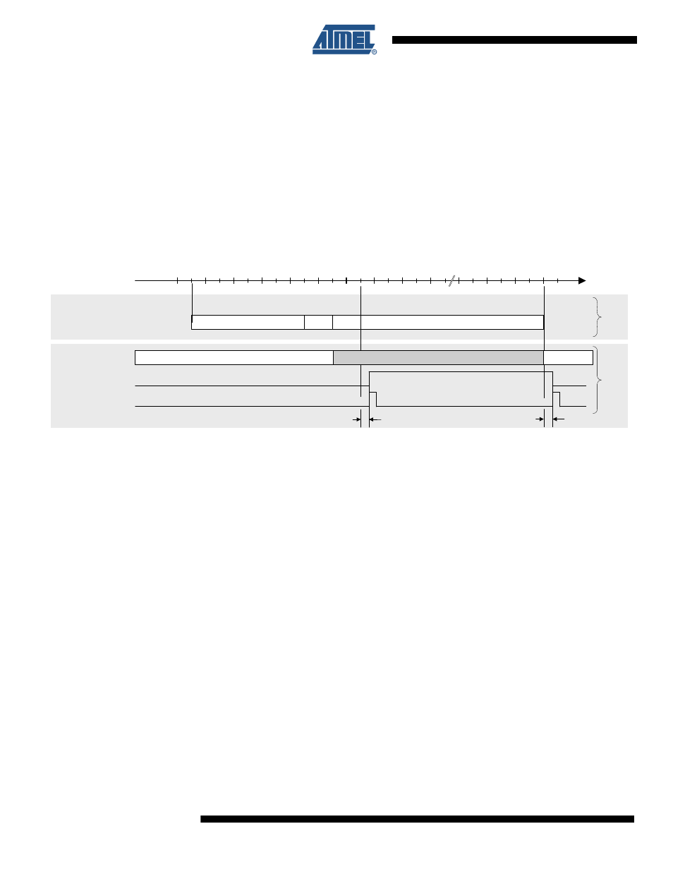
To determine the exact timing of an incoming frame, e.g. for beaconing networks, the reception
of this frame can be signaled to the microcontroller via pin 10 (DIG2). The pin turns from L to H
after a detection of a valid PHR. When enabled, DIG2 is set to DIG2 = H at the same time as
IRQ_2 (RX_START), even if IRQ_2 is disabled. The pin remains high for the length of the frame
receive procedure, see
Figure 11-12. Timing of RX_START and DIG2 for RX Frame Time Stamping
Note:
Timing figures refer to
12.4 “Digital Interface Timing Characteristics” on page 157
.
This function is enabled with register bit IRQ_2_EXT_EN (register 0x04) set. Pin 10 (DIG2)
could be connected to a timer capture unit of the microcontroller.
If this pin is not used for RX Frame Time Stamping it can be configured for Antenna Diversity.
Otherwise this pin is pulled-down to digital ground.
128
160
192
0
192 + m * 32
Time [µs]
RX
Fr
am
e
on Air
IRQ_2 (RX_START)
t
IRQ
RX_ON
RX_ON
IRQ
TRX_STATE
Interrupt latency
Preamble
SFD
PHR
PSDU (250 kb/s)
4
1
1
m < 128
Number of Octets
Frame Content
TRX_END
t
IRQ
BUSY_RX
DIG2 (RX Frame Time Stamp)