Rainbow Electronics AT86RF401 User Manual
Smart rf, Features, Applications
1
Features
•
RF Frequency Range of 264–456 MHz
•
6 dBm RF Output into Matched Antenna
•
RF Output Power Adjustable over 36 dB with 1 dB Resolution
•
Phase-locked Loop (PLL) Based Frequency Synthesizer
•
Supports OOK Modulation
•
Data Bandwidth of Up to 10 Kbps Manchester
•
2-volt Operation
•
8-bit AVR
â
RISC Microcontroller Core
•
Minimal External Components
•
Space-saving 20-lead TSSOP
•
2 KB (1K x 16) of Flash Program Memory
•
128 Bytes of EEPROM
•
128 Bytes of SRAM
•
In-system Programmable Data and Program Memory
•
Six I/Os (Serial I/F, LED Drive Outputs, Button Input Interrupts)
•
Low Battery Detect and Brown-out Protection
•
Software Fine-tuning of VCO Tank Circuit
Applications
•
Remote Keyless Entry (RKE) Transmitters
•
Wireless Security Systems
•
Home Appliance Control (Lighting Control, Ceiling Fans)
•
Radio Remote Control (Hobby, Toys)
•
Garage Door Openers
•
Wireless PC Peripherals (Keyboard, Mouse)
•
Telemetry (Tire Pressure, Utility Meter, Asset Tracking)
Description
The Atmel AT86RF401 Smart RF
™
Microtransmitter is a highly integrated, low-cost RF
transmitter, combined with an AVR
RISC microcontroller. It requires only a crystal, a
single LiMnO
2
coin cell (CR2032 or similar), three capacitors, an inductor and a tuned-
loop antenna to implement a complete on-off keyed (OOK) wireless RF data
transmitter.
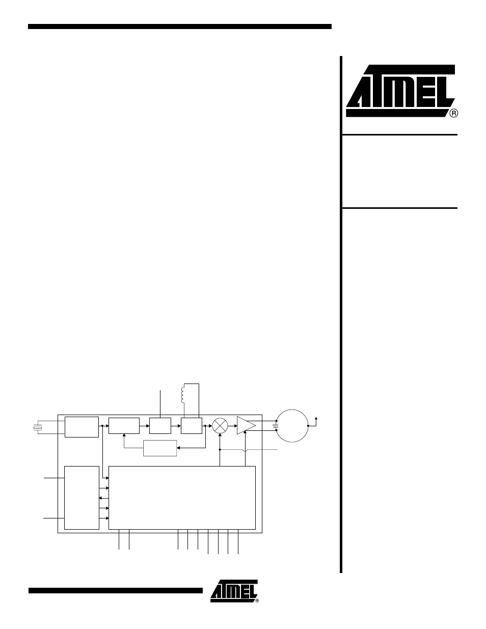
Figure 1. Block Diagram
PHASE
DETECTOR
OSCILLATOR
LOOP
FILTER
VCO
PRESCALER
÷
24
RF
AMP
LOOP FIL
CLOCK
RESET
WATCHDOG
LOW-VOLTAGE DETECT
BROWN-OUT PROTECT
AVR RISC
µC
2 KB Flash Program Memory
128 Bytes EEPROM Data Memory
L1
L2
DATA
GAIN
TRIM
POWER
SUPPLY
SUPERVISOR
XTAL/CLK
XTALB
AVDD
AGND
ANT
ANTB
B
+
D
VDD
DGND
IO5
IO4
IO3
SCK/IO2
SDO/IO1
SDI/IO0
RESETB
CFIL
Smart RF
™
Wireless Data
Microtransmitter
AT86RF401
Preliminary
1424D–RKE–09/02
Document Outline
- Features
- Applications
- Description
- Absolute Maximum Ratings*
- DC Characteristics
- Analog/RF Specs
- Functional Description
- Reset and Interrupt Handling
- Memory Programming
- Serial Programming Algorithm
- Data EEPROM Access from the AVR
- AVR Core
- Architectural Overview
- General-purpose Register File
- Arithmetic Logic Unit (ALU)
- In-system Self- programmable Flash Program Memory
- SRAM Data Memory
- Program and Data Addressing Modes
- Register Direct, Single Register Rd
- Register Direct, Two Registers Rd and Rr
- I/O Direct
- Data Direct
- Data Indirect with Displacement
- Data Indirect
- Data Indirect with Pre-decrement
- Data Indirect with Post-increment
- Constant Addressing Using the LPM Instruction
- Indirect Program Addressing, IJMP and ICALL
- Relative Program Addressing, RJMP and RCALL
- EEPROM Data Memory
- Memory Access Times and Instruction Execution Timing
- I/O Memory
- I/O and Control Registers
- Transmitter Control Register Descriptions
- EEPROM Control Register Descriptions
- Bit Timer Register Descriptions
- Bit Timer Count Register – BTCNT
- Bit Timer Control Register – BTCR
- Watchdog Timer Control Register – WDTCR
- I/O Enable Register – IO_ENAB
- I/O Data Out Register – IO_DATOUT
- I/O Data In Register – IO_DATIN
- AVR Configuration Register – AVR_CONFIG
- Button Detect Register – B_DET
- Battery Low Configuration Register – BL_CONFIG
- The Stack Pointer – SP
- The Status Register – SREG
- Ordering Information
- Package Drawing