2 wake-up procedure, 3 pll_on and rx_on states – Rainbow Electronics AT86RF231 User Manual
Page 40
40
8111A–AVR–05/08
AT86RF231
7.1.4.2
Wake-up Procedure
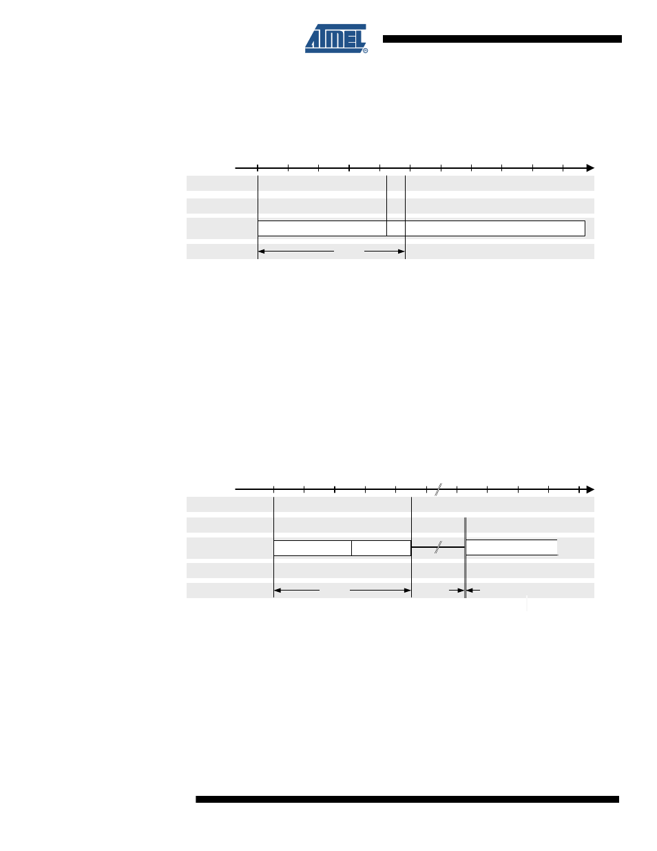
The wake-up procedure from SLEEP state is shown in
.
Figure 7-4.
Wake-up Procedure from SLEEP State
The radio transceivers SLEEP state is left by releasing pin SLP_TR to logic low. This restarts the
XOSC and DVREG. After t
TR2
= 240 µs (typ.) the radio transceiver enters TRX_OFF state. The
internal clock signal is available and provided to pin 17 (CLKM), if CLKM was enabled.
This procedure is similar to the Power-On Procedure. However the radio transceiver continues
the state change automatically to the TRX_OFF state. During this the filter-tuning network (FTN)
calibration is performed. Entering TRX_OFF state is signaled by IRQ_4 (AWAKE_END), if this
interrupt was enabled by the appropriate mask register bit.
7.1.4.3
PLL_ON and RX_ON States
The transition from TRX_OFF to PLL_ON and RX_ON mode is shown in
Figure 7-5.
Transmission from TRX_OFF to PLL_ON and RX_ON State
Note:
If TRX_CMD = RX_ON in TRX_OFF state RX_ON state is entered immediately, even if the PLL
has not settled.
In TRX_OFF state, entering the commands PLL_ON or RX_ON initiates a ramp-up sequence of
the internal 1.8V voltage regulator for the analog domain (AVREG). RX_ON state can be
entered any time from PLL_ON state regardless whether the PLL has already locked, which is
indicated by IRQ_0 (PLL_LOCK).
0
Event
State
Block
100
CLKM on
400
Time [µs]
Time
t
TR2
TRX_OFF
IRQ_4 (AWAKE_END)
SLP_TR = L
SLEEP
200
XOSC, DVREG
XOSC, DVREG
FTN
0
Event
State
Block
100
Time [µs]
Time
t
TR4
IRQ_0 (PLL_LOCK)
TRX_OFF
AVREG
Command
PLL_ON
PLL
RX
PLL_ON
R_ON
t
TR8
RX_ON