2 user accessible frame content – Rainbow Electronics AT86RF231 User Manual
Page 108
108
8111A–AVR–05/08
AT86RF231
9.3.2
User accessible Frame Content
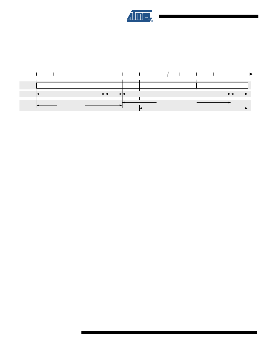
The AT86RF231 supports an IEEE 802.15.4 compliant frame format as shown in
.
Figure 9-4.
AT86RF231 Frame Structure
Notes:
1. Stored into Frame Buffer for TX operation
2. Stored into Frame Buffer during frame reception.
A frame comprises two sections, the radio transceiver internally generated SHR field and the
user accessible part stored in the Frame Buffer. The SHR contains the preamble and the SFD
field. The variable frame section contains the PHR and the PSDU including the FCS, see
tion 8.2 “Frame Check Sequence (FCS)” on page 85
.
The Frame Buffer content differs depending on the direction of the communication (receive or
transmit). To access the data follow the procedures described in
.
During frame reception, the payload and the link quality indicator (LQI) value of a successfully
received frame are stored in the Frame Buffer. The radio transceiver appends the LQI value to
the frame data after the last received octet. The frame length information is not stored in the
Frame Buffer. When using the Frame Buffer access mode to read the Frame Buffer content, the
frame length information is placed before the payload.
If the SRAM read access is used to read an RX frame, the frame length field (PHR) cannot be
accessed. The SHR (except the SFD used to generate the SHR) can generally not be read by
the microcontroller.
For frame transmission, the PHR and the PSDU needs to be stored in the Frame Buffer. The
PHR byte is the first byte in the Frame Buffer and must be calculated based on the PHR and the
PSDU. The maximum frame size supported by the radio transceiver is 128 bytes. If the
TX_AUTO_CRC_ON bit is set in register 0x05 (PHY_TX_PWR), the FCS field of the PSDU is
replaced by the automatically calculated FCS during frame transmission. That's why there is no
need to write the FCS field when using the automatic FCS generation.
To manipulate individual bytes of the Frame Buffer a SRAM write access can be used instead.
For non IEEE 802.15.4 compliant frames, the minimum frame length supported by the radio
transceiver is one byte (Frame Length Field + 1 byte of data).
Preamble Sequence
SFD
PHR
(1)
Payload
LQI
(2)
FCS
0
4
5
6
n + 3
n + 5
n + 6
Frame
Access
SHR not accesible
RX: Frame Buffer content
PHY generated
Length [octets]
Duration
4 octets / 128 µs
1
n octets / n • 32 µs (n <= 128)
1
TX: Frame Buffer content