Operating modes, 1 basic operating mode, 1 state control – Rainbow Electronics AT86RF231 User Manual
Page 33: Section 7. “operating modes” on, Trx_off, P_on, Sleep, Busy_tx, Pll_on, Rx_on_noclk
33
8111A–AVR–05/08
AT86RF231
7.
Operating Modes
7.1
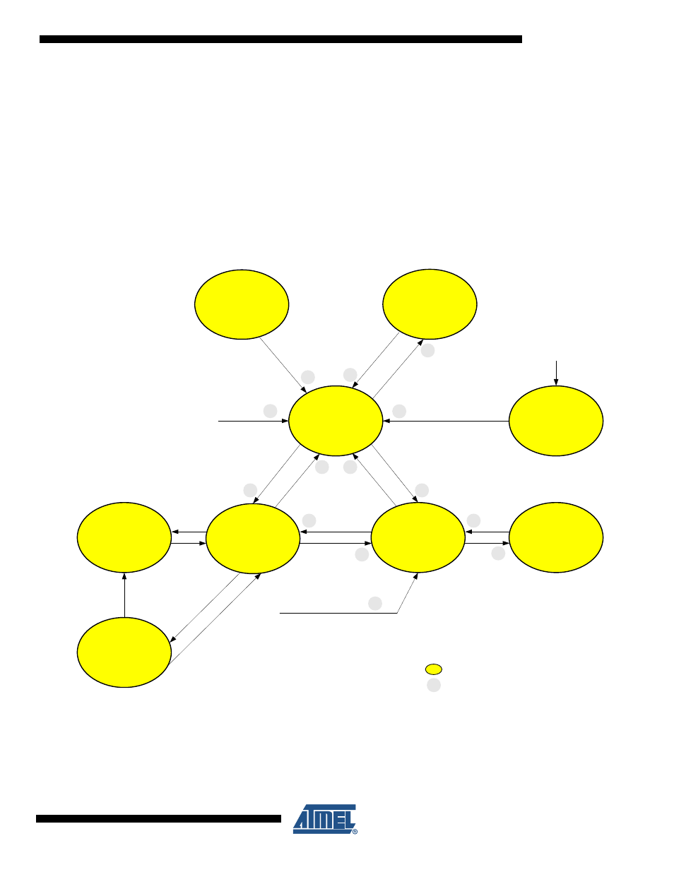
Basic Operating Mode
This section summarizes all states to provide the basic functionality of the AT86RF231, such as
receiving and transmitting frames, the power up sequence and sleep. The Basic Operating
Mode is designed for IEEE 802.15.4 and ISM applications; the corresponding radio transceiver
states are shown in
.
Figure 7-1.
Basic Operating Mode State Diagram (for timing refer to
7.1.1
State Control
The radio transceiver states are controlled either by writing commands to register bits
TRX_CMD (register 0x02, TRX_STATE), or directly by two signal pins: pin 11 (SLP_TR) and
2
T
R
X
_O
F
F
S
L
P
_T
R
=
H
S
L
P
_T
R
=
L
P
L
L
_O
N
RX_ON
PLL_ON
TRX_OFF
(Clock State)
XOSC=ON
Pull=OFF
R
X
_O
N
P_ON
(Power-on after V
DD
)
XOSC=ON
Pull=ON
SLEEP
(Sleep State)
XOSC=OFF
Pull=OFF
(all states except P_ON)
FORCE_TRX_OFF
(all states except SLEEP)
SHR
Detected
Frame
End
Frame
End
BUSY_TX
(Transmit State)
PLL_ON
(PLL State)
TX_START
or
T
R
X
_O
F
F
T
R
X
_O
F
F
1
3
4
5
7
6
8
9
11
10
RX_ON_NOCLK
(Rx Listen State)
CLKM=OFF
SL
P_
TR =
H
S
LP_
TR
=
L
SHR
De
tect
ed
12
13
/RST = H
FORCE_PLL_ON
(all states except SLEEP,
P_ON, TRX_OFF, RX_ON_NOCLK)
14
SLP_TR = H
Legend:
Blue: SPI Write to Register TRX_STATE (0x02)
Red: Control signals via IC Pin
Green: Event
Basic Operating Mode States
State transition number, see Table 7-1
RX_ON
(Rx Listen State)
BUSY_RX
(Receive State)
RESET
(from all states)
/RST = L
X