Module description, 1 receiver (rx), 1 overview – Rainbow Electronics AT86RF231 User Manual
Page 101
101
8111A–AVR–05/08
AT86RF231
9.
Module Description
9.1
Receiver (RX)
9.1.1
Overview
The AT86RF231 receiver is split into an analog radio front end and a digital base band proces-
sor (RX BBP), see
.
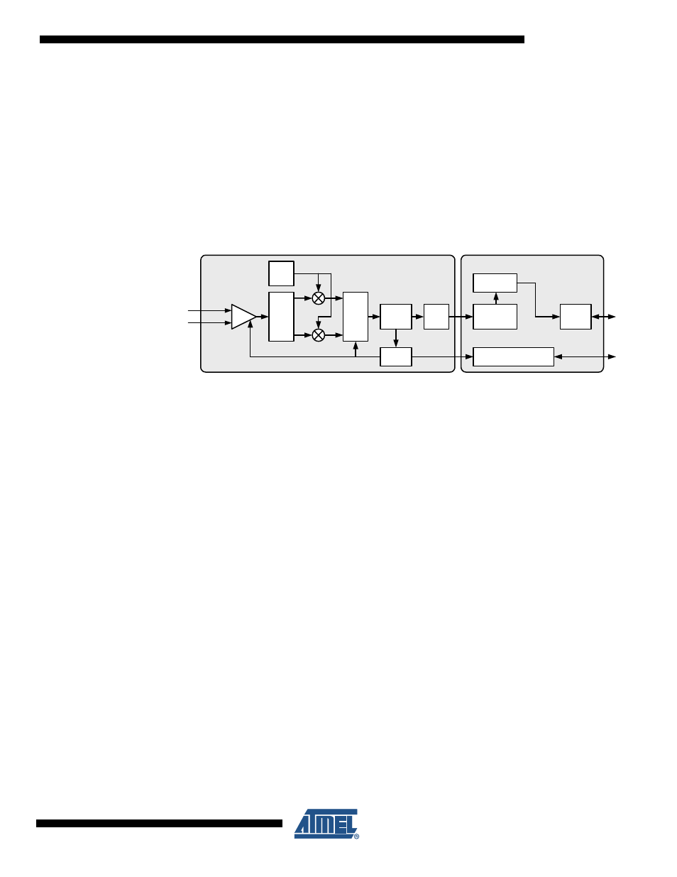
Figure 9-1.
Receiver Block Diagram
The differential RF signal is amplified by a low noise amplifier (LNA), filtered (PPF) and down
converted to an intermediate frequency by a mixer. Channel selectivity is performed using an
integrated band pass filter (BPF). A limiting amplifier (Limiter) provides sufficient gain to over-
come the DC offset of the succeeding analog-to-digital converter (ADC) and generates a digital
RSSI signal. The ADC output signal is sampled and processed further by the digital base band
receiver (RX BBP).
The RX BBP performs additional signal filtering and signal synchronization. The frequency offset
of each frame is calculated by the synchronization unit and is used during the remaining receive
process to correct the offset. The receiver is designed to handle frequency and symbol rate devi-
ations up to ±120 ppm, caused by combined receiver and transmitter deviations. For details
refer to
Section 12.5 “General RF Specifications” on page 158
parameter 12.5.8. Finally the sig-
nal is demodulated and the data are stored in the Frame Buffer.
In Basic Operating Mode, refer to
Section 7.1 “Basic Operating Mode” on page 33
, the reception
of a frame is indicated by an interrupt IRQ_2 (RX_START). Accordingly its end is signalized by
an interrupt IRQ_3 (TRX_END). Based on the quality of the received signal a link quality indica-
tor (LQI) is calculated and appended to the frame, refer to
Section 8.6 “Link Quality Indication
. Additional signal processing is applied to the frame data to provide further
status information like ED value (register 0x07, ED_LEVEL) and FCS correctness (register
0x06, PHY_RSSI).
Beyond these features the Extended Operating Mode of the AT86RF231 supports address filter-
ing and pending data indication. For details refer to
Section 7.2 “Extended Operating Mode” on
LNA
PPF
BPF
Limiter
ADC
AGC
RSSI
RFP
RFN
Analog Domain
Digital Domain
SPI
RX BBP
Frame
Buffer
LO
Control, Registers
SPI
I/F
µC
I/F