Pin-out diagram – Rainbow Electronics AT86RF231 User Manual
Page 2
2
8111A–AVR–05/08
AT86RF231
1.
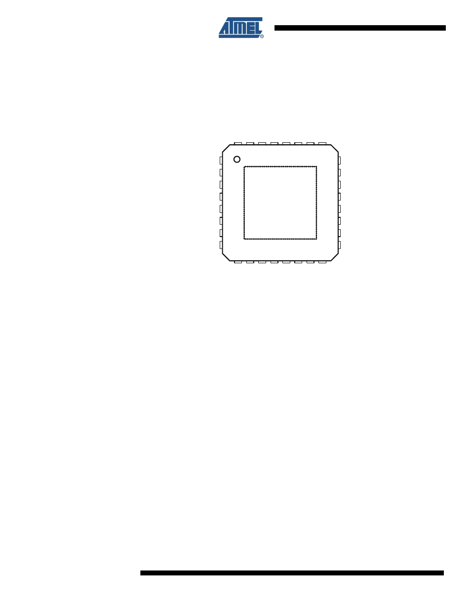
Pin-out Diagram
Figure 1-1.
AT86RF231 Pin-out Diagram
Note:
The exposed paddle is electrically connected to the die inside the package. It shall be soldered to
the board to ensure electrical and thermal contact and good mechanical stability.
32
24
23
22
21
20
19
18
17
1
2
3
4
5
6
7
8
A T86R F231
C L K M
D V S S
D IG 3
D IG 4
A V S S
A V S S
R FP
R FN
D V S S
/R S T
DI
G
1
DI
G
2
SL
P_
T
R
DV
S
S
DV
D
D
DV
D
D
DE
V
D
D
DV
S
S
S C L K
M IS O
D V S S
M O S I
/S E L
IR Q
XT
AL
2
XT
AL
1
AVSS
EVD
D
AVD
D
AVSS
AVSS
AVSS
31 30 29 28 27 26 25
9 10 11 12 13 14 15 16
A V S S
exposed paddle
See also other documents in the category Rainbow Electronics Wireless Headsets:
- RC2000 (2 pages)
- Т7023 (12 pages)
- Т7024 (20 pages)
- RC2200 (17 pages)
- RF01 (26 pages)
- RC1090 (17 pages)
- U3741BM (32 pages)
- U3742BM (32 pages)
- RAM01 (7 pages)
- RF22 (92 pages)
- RC1180-MBUS (28 pages)
- RFM01 (8 pages)
- RF12B (36 pages)
- RC1290 (17 pages)
- RC2300-ZNM (1 page)
- RF12 (31 pages)
- T48C862-R3 (107 pages)
- RF02 (24 pages)
- T48C862-R8 (107 pages)
- RFM12 (10 pages)
- U3745BM (29 pages)
- T5744 (19 pages)
- RFM12B (10 pages)
- U2745B (9 pages)
- T48C862-R4 (107 pages)
- RA01 (19 pages)
- T5754 (11 pages)
- U2741B (9 pages)
- RFM02 (8 pages)
- RC2100 (22 pages)
- RF модули диапазона ISM (4 pages)
- T5761 (35 pages)
- BTM -17х (5 pages)
- ATA8401 (12 pages)
- BTM -22х (7 pages)
- ATA5575M1 (7 pages)
- AT88RF1354 (50 pages)
- ATA5812 (90 pages)
- AT86RF401 (50 pages)
- AT76C551 (77 pages)
- BTM -250 (6 pages)
- AT75C310 (132 pages)
- AT75C320 (13 pages)
- BTM -140 (6 pages)