6 crystal oscillator (xosc), 1 overview, 2 integrated oscillator setup – Rainbow Electronics AT86RF231 User Manual
Page 116: Section 9.6, Section 9.6 “crystal
116
8111A–AVR–05/08
AT86RF231
9.6
Crystal Oscillator (XOSC)
The main crystal oscillator features are:
• 16 MHz amplitude controlled crystal oscillator
• 215 µs typical settling time after leaving SLEEP state
• Configurable trimming capacitance array
• Configurable clock output (CLKM)
9.6.1
Overview
The crystal oscillator generates the reference frequency for the AT86RF231. All other internally
generated frequencies of the radio transceiver are derived from this unique frequency. There-
fore, the overall system performance is mainly determined by the accuracy of crystal reference
frequency. The external components of the crystal oscillator should be selected carefully and the
related board layout should be done with caution (see
Section 5. “Application Circuits” on page
The register 0x12 (XOSC_CTRL) provides access to the control signals of the oscillator. Two
operating modes are supported. It is recommended to use the integrated oscillator setup as
described in
; nevertheless a reference frequency can be fed to the inter-
nal circuitry by using an external clock reference as shown in
9.6.2
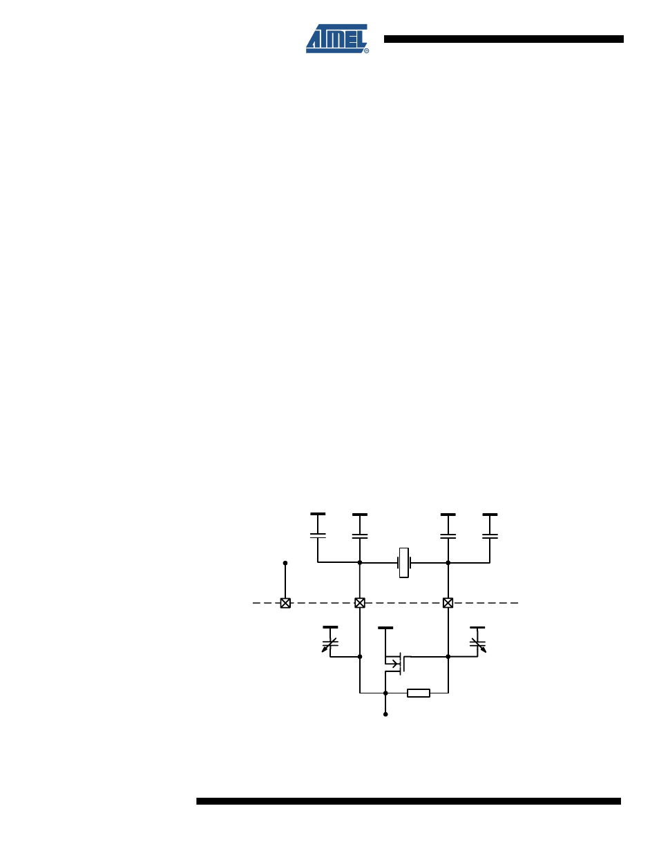
Integrated Oscillator Setup
Using the internal oscillator, the oscillation frequency depends on the load capacitance between
the crystal pins XTAL1 and XTAL2. The total load capacitance C
L
must be equal to the specified
load capacitance of the crystal itself. It consists of the external capacitors CX and parasitic
capacitances connected to the XTAL nodes.
shows all parasitic capacitances, such as PCB stray capacitances and
the pin input capacitance, summarized to C
PAR
.
Figure 9-7.
Simplified XOSC Schematic with External Components
CX
CX
16MHz
XTAL2
XTAL1
EVDD
C
TRIM
C
TRIM
C
PAR
C
PAR
AT86RF231
PCB
XTAL_TRIM[3:0]
EVDD
V
DD
XTAL_TRIM[3:0]