Microcontroller interface, Section 6. “microcontroller – Rainbow Electronics AT86RF231 User Manual
Page 16
16
8111A–AVR–05/08
AT86RF231
6.
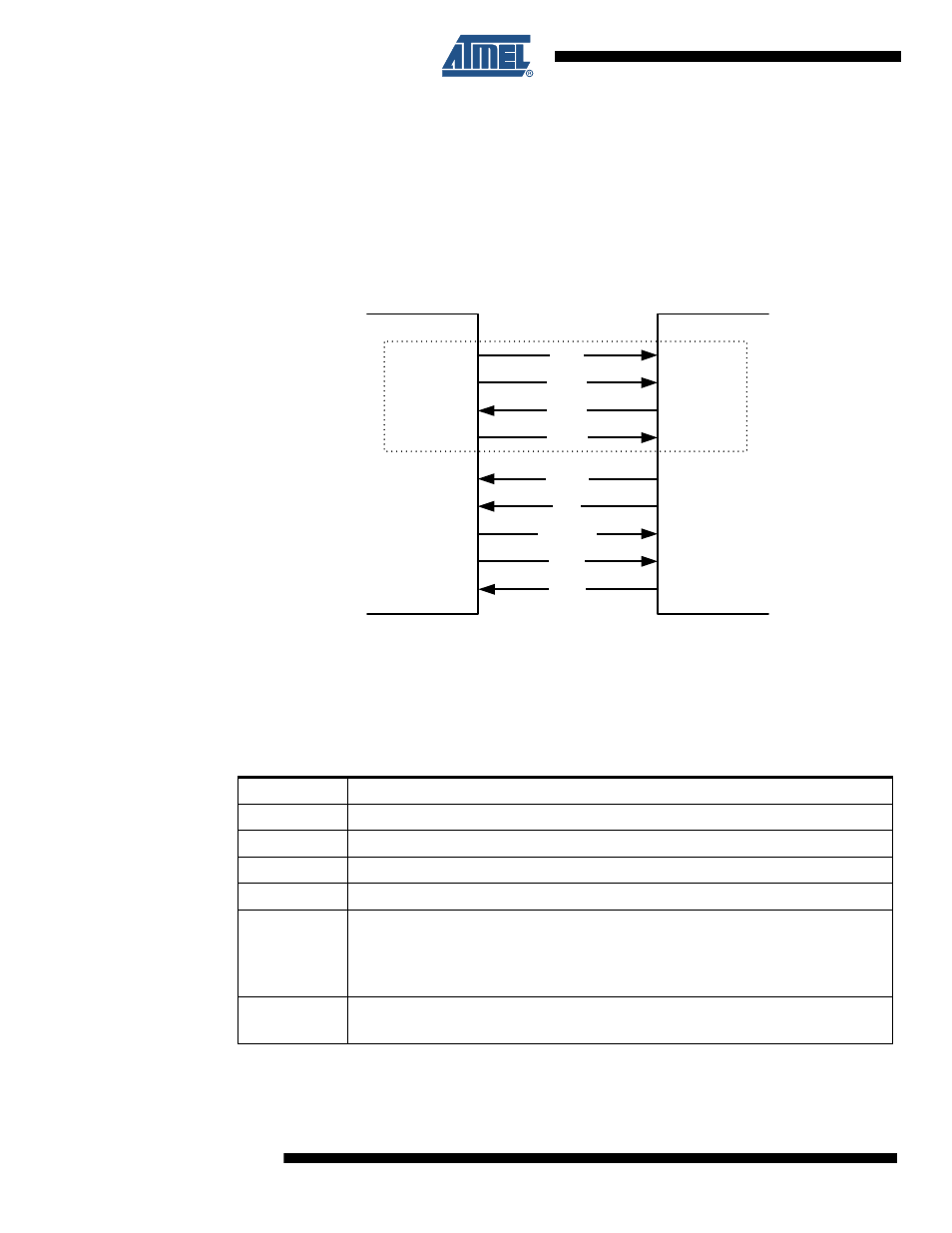
Microcontroller Interface
This section describes the AT86RF231 to microcontroller interface. The interface comprises a
slave SPI and additional control signals; see
. The SPI timing and protocol
are described below.
Figure 6-1.
Microcontroller to AT86RF231 Interface
Microcontrollers with a master SPI such as Atmel's AVR family interface directly to the
AT86RF231. The SPI is used for register, Frame Buffer, SRAM and AES access. The additional
control signals are connected to the GPIO/IRQ interface of the microcontroller.
introduces the radio transceiver I/O signals and their functionality.
Table 6-1.
Signal Description of Microcontroller Interface
Signal
Description
/SEL
SPI select signal, active low
MOSI
SPI data (master output slave input) signal
MISO
SPI data (master input slave output) signal
SCLK
SPI clock signal
CLKM
Clock output, refer to
usable as:
-microcontroller clock source
-high precision timing reference
-MAC timer reference
IRQ
Interrupt request signal, further used as:
-Frame Buffer Empty Indicator, refer to
Microcontroller
AT86RF231
/SEL
MOSI
MISO
SCLK
CLKM
IRQ
SLP_TR
MOSI
MISO
SCLK
GPIO1/CLK
GPIO2/IRQ
GPIO3
MOSI
MISO
SCLK
CLKM
IRQ
SLP_TR
/RST
GPIO4
SPI
/SEL
/SEL
/RST
DIG2
GPIO5
DIG2
SP
I -
Mast
er
SP
I -
S
lav
e