5 rx/tx indicator, 1 overview, 2 external rf-front end control – Rainbow Electronics AT86RF231 User Manual
Page 147: Section 11.5
147
8111A–AVR–05/08
AT86RF231
11.5
RX/TX Indicator
The main features are:
• RX/TX Indicator to control an external RF Front-End
• Microcontroller independent RF Front-End Control
• Provide TX Timing Information
11.5.1
Overview
While IEEE 802.15.4 is a low cost, low power standard, solutions supporting higher transmit out-
put power are occasionally desirable. To simplify the control of an optional external RF front-
end, a differential control pin pair can indicate that the AT86RF231 is currently in transmit mode.
The control of an external RF front-end is done via digital control pins DIG3/DIG4. The function
of this pin pair is enabled with register bit PA_EXT_EN (register 0x04, TRX_CTRL_1). While the
transmitter is turned off pin 1 (DIG3) is set to low level and pin 2 (DIG4) to high level. If the radio
transceiver starts to transmit, the two pins change the polarity. This differential pin pair can be
used to control PA, LNA, and RF switches.
If the AT86RF231 is not in a receive or transmit state, it is recommended to disable register bit
PA_EXT_EN (register 0x04, TRX_CTRL_1) to reduce the power consumption or avoid leakage
current of external RF switches and other building blocks, especially during SLEEP state. If reg-
ister bits PA_EXT_EN = 0, output pins DIG3/DIG4 are pulled-down to analog ground.
11.5.2
External RF-Front End Control
Using an external RF front-end including a power amplifier (PA) it may be required to adjust the
setup time of the external PA relative to the internal building blocks to optimize the overall power
spectral density (PSD) mask.
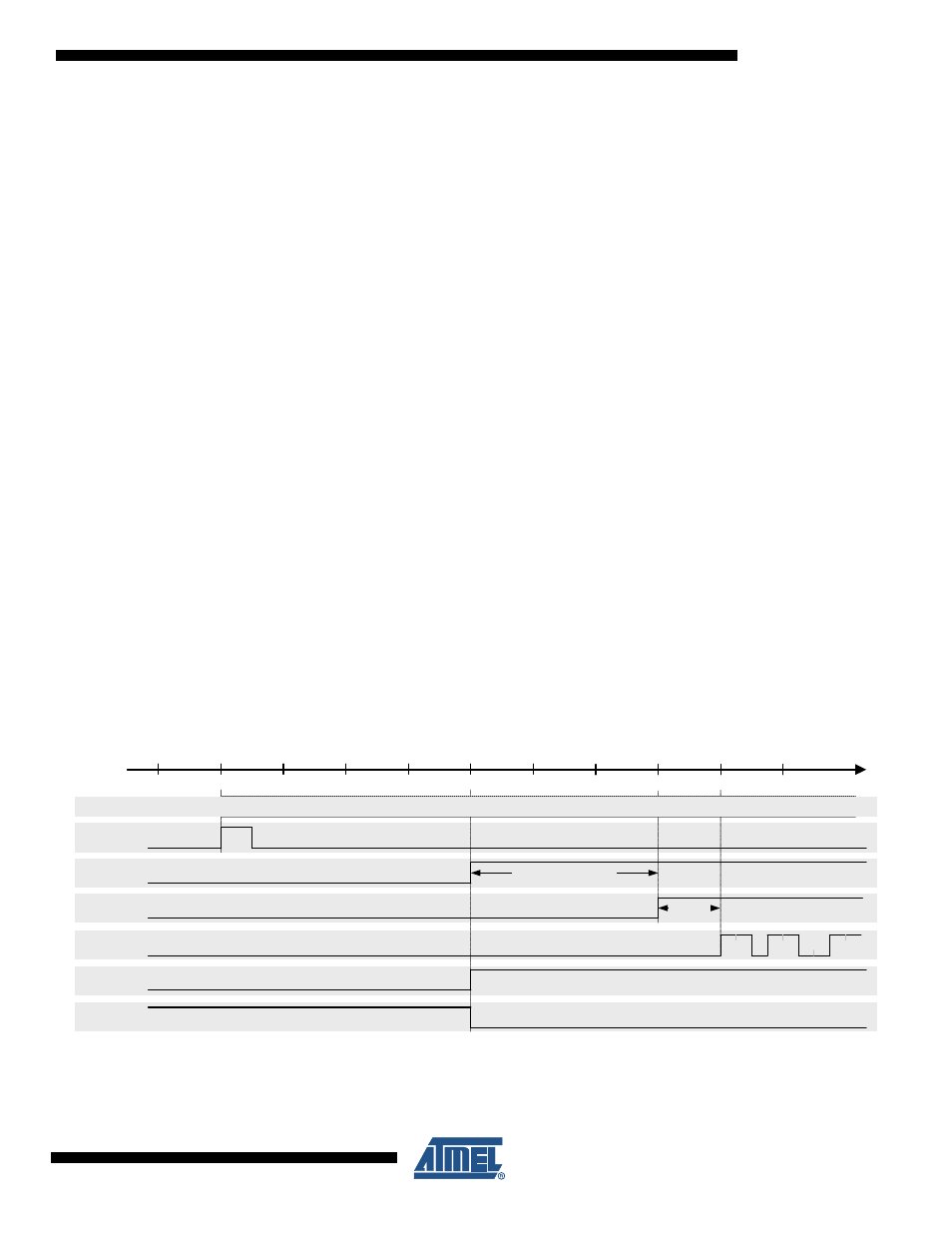
Figure 11-11. TX Power Ramping Control for RF Front-Ends
The start-up sequence of the individual building blocks of the internal transmitter is shown in
, where transmission is actually initiated by the rising edge of pin 11
(SLP_TR). The radio transceiver state changes from PLL_ON to BUSY_TX and the PLL settles
0
6
8
10
TRX_STATE
SLP_TR
PLL_ON
2
12
14
16
18
Length [µs]
PA buffer
4
PA
PA_BUF_LT
PA_LT
DIG3
DIG4
Modulation
1 1
1 1
1 1
0 0
0
BUSY_TX