Positioning the media sensors – Printronix SL4M User Manual
Page 44
44
Chapter
2
Positioning the Media Sensors
3.
Remove the printhead alignment tool (yellow screwdriver) from the tool
clip.
4.
Use the printhead alignment tool to turn the printhead alignment dial.
Turn the printhead alignment dial UP for THICKER stocks and DOWN for
THINNER stocks.
5.
Close the pivoting deck by rotating the deck lock lever fully clockwise.
6.
Run a print test, such as the checkerboard or gray scale.
See “Printer Tests” on page 145.
7.
If necessary repeat steps 4 to 6 until the desired alignment is achieved.
8.
Lower the media cover.
Positioning the Media Sensors
Your printer is equipped with a media sensor assembly that detects the
top-of-form position on media with label length indicators (gaps, notches,
holes, or black marks). These sensors also detect when a Paper Out
condition exists.
See page 221 for media and label length indicators.
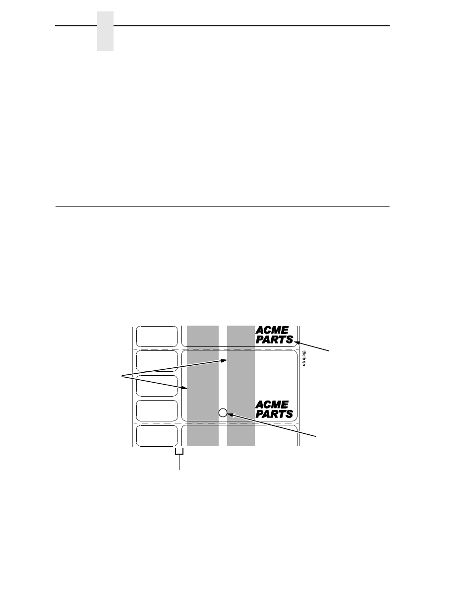
The media sensors should not be placed in the path of media features that
could cause false gap detection or paper out faults. Such features are dark
pre-printing, rounded die-cut label corners, vertical gaps associated with
side-by-side labels, and extraneous cut-outs, as shown below.
Vertical Gap and
Rounded Die-cut
Label Corners
Extraneous Cut-out
Dark Pre-printing
Position the media
sensors in either of
the grey shaded
areas.