Installing “gain setting” shorting jumpers, Installing “gain setting – Ohaus I150-S Indicator User Manual
Page 9
9
Installing “Gain Setting”
Installing “Gain Setting”
Installing “Gain Setting”
Installing “Gain Setting”
Installing “Gain Setting”
Shorting Jumpers
Shorting Jumpers
Shorting Jumpers
Shorting Jumpers
Shorting Jumpers
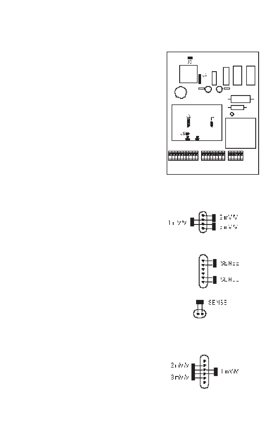
The gain setting for the I150 must be set
to match the output signal of the load
receiver(s) being used. There are three
possible configurations:
1.
Single load receiver without SENSE.
2.
Single load receiver with SENSE.
3.
Dual load receivers.
The gain setting is selected by installing
shorting jumpers on connectors “J6”, “J5”
and “J2” of the main circuit board as
necessary. Refer to the diagrams and use
the following as a guide.
The factory default gain setting has been
set to single load receiver, at 2mV/V,
without SENSE.
J5
J2
J6
J2
For Single Load Receiver Operation:
For Single Load Receiver Operation:
For Single Load Receiver Operation:
For Single Load Receiver Operation:
For Single Load Receiver Operation:
Install one shorting jumper on connector
“J5” in the position labeled with the gain
that matches the output of the load re-
ceiver in use: 1, 2 or 3 mV/V.
If the SENSE connection is being used,
install two shorting jumpers on “J2”, and
one on “J6” as shown in the diagram.
For Dual Load Receiver Operation:
For Dual Load Receiver Operation:
For Dual Load Receiver Operation:
For Dual Load Receiver Operation:
For Dual Load Receiver Operation:
Install one shorting jumper on “J5” as for
one cell operation. Install one shorting
jumper on “J2” in the position labeled with
the gain matching the output of the sec-
ond load receiver: 1, 2 or 3 mV/V.
NOTE: During dual receiver operation,
SENSE jumpers must be removed.