Zero adjustment, Calibration – Ohaus I150-S Indicator User Manual
Page 37
37
Calibration
Calibration
Calibration
Calibration
Calibration
Before beginning, you must know the
calibration point that was entered in the
“SEtUP” submenu, and have a calibration
weight of that value on hand. If 3-point
linearization is to be performed, you will
also need a weight equal to 1/2 of the
calibration point.
1.
When you select “Calib” from the
calibration submenu, “CAL 0” will be
displayed indicating than no load
should be on the load receiver.
2.
With no load on the load receiver,
press
ENTER
.
Zero Adjustment
Zero Adjustment
Zero Adjustment
Zero Adjustment
Zero Adjustment
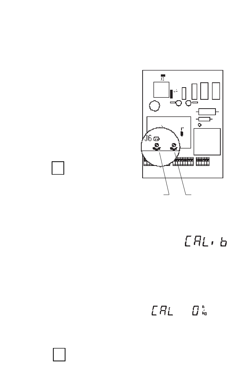
In order to adjust the load cell zero, the
I150 cover must be open and you will
need the small screwdriver provided in
the accessory kit. Make sure there is no
load on the load receiver.
1.
Locate the zero adjustment screws
on the main circuit board as shown in
the illustration.
2.
Turn the appropriate zero adjustment
screw (LOAD CELL 1, or LOAD CELL
2) Clockwise to increase and Counter-
clockwise to decrease the displayed
value. Adjust until it is anywhere be-
tween 1% and 5%.
3.
When the displayed value is correct,
press
ENTER
to exit dead load.
Proceed to the Calibration section
and recalibrate the indicator.
Cell #2
Zero
Adjustment
Cell #1
Zero
Adjustment
ENTER
ENTER
ENTER
ENTER
ENTER
ENTER
ENTER
ENTER
ENTER
ENTER