Connect hot (black) wires, Figure 3-20, Generator input wiring to a single inverter –37 – Xantrex Technology SW Plus 4024 User Manual
Page 119: Figure 3-20, “generator input, Sine wave plus inverter/charger
AC Wiring
976-0043-01-02
3–37
b) from the neutral in the generator disconnect to the inverter
NEUTRAL 2 terminal.
3.
Connect HOT (black) wires:
a) from the generator GEN HOT OUT terminal to the circuit
breaker in the generator disconnect, and
b) from the circuit breaker in the generator disconnect to the inverter
AC2 GEN terminal.
4.
Torque all inverter terminal block connections to 25 inch-pounds.
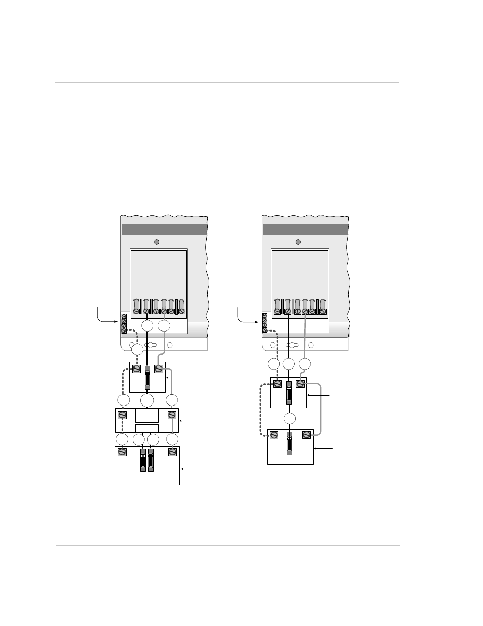
Figure 3-20 Generator Input Wiring to a Single Inverter
AC
GROUND
BAR
(INSIDE)
Sine Wave Plus
Inverter/Charger
Generator
Disconnect Switch
(Optional)
G
N
GROUND
NEUTRAL
GEN HOT OUT
120/240 Vac
GENERATOR
L1
L2
G
HOT OUT
N
HOT IN
1a
2a
3a
Step-down
Autotransformer
(Optional)
2b
3b
3c
AC
GROUND
BAR
(INSIDE)
Sine Wave Plus
Inverter/Charger
AC TERMINAL
BLOCK
IN
V
O
U
T
NEUT
RAL
OUT
NEUT
RAL
2
NEUT
RAL
1
AC1
GRI
D
AC2
GEN
AC TERMINAL
BLOCK
IN
V
O
U
T
NEUT
RAL
OUT
NEUT
RAL
2
NEUT
RAL
1
AC1
GRI
D
AC2
GEN
1c
3d
2c
GROUND
NEUTRAL
GEN HOT OUT
120 Vac ONLY
GENERATOR
G
N
3b
2c
1b
1c
3a
Generator
Disconnect Switch
(Optional)
Generator connections using a
T240, a generator disconnect and
a 120/240 Vac Generator
Generator connections using a
generator disconnect and a
120 Vac Generator